–
15
–
FIGURE 19
[3e] INSTALLATION OF FM TYPE
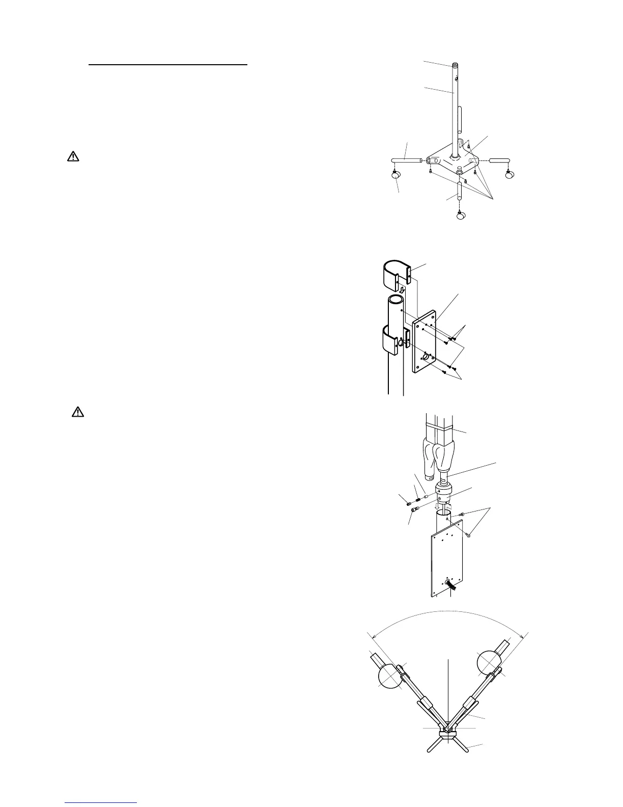
1. POLE ASSEMBLY INSTALLATION
(FIGURE 17)
1-1. Attach four legs bars to the pole base and secure them by
hex socket head bolts. (Align the hole on bottom of base
with the threaded hole on the leg bar.).
:
TWO LONGER LEG BARS MUST BE ATTACHED TO
THE WIDER ENDS OF THE BASE.
2. Attach the caster to each leg end.
2. CONTROL BOX MOUNTING PLATE
(FIGURE 18)
2-1. Set the control box mounting plate over the access hole
of the pole at the short leg side, as 3 wires of power sup-
ply come out from access hole. Secure two screws above
and below the access hole.
2-2. Slide the supporter of mounting plate down to the oppo-
site side of mounting plate, and secure with two screws
beside the access hole.
3. ARM ASSEMBLY INSTALLATION
FIGURE 17
FIGURE 18
:
DO NOT RELEASE ARM HOLDING BAND UNTIL
THE X-RAY HEAD HAS BEEN INSTALLED. BAL-
ANCE ARM ASSEMBLY IS SPRING LOADED AND
CAN CAUSE EQUIPMENT DAMAGE AND INJURY
IF NOT HANDLED IN THE PROPER MANNER.
3-1. Insert the shaft of balance arm with pole
bushing attached into the pole as the wires
go through the access hole of control box
mounting plate.
3-2. Keeping the arm at the position (a) of FIGURE 20.
3-3. Fix the pole bushing by two mounting screws on the pole.
3-4. Conrm the swing range of the arm is as FIGURE 20.
4. HEAD INSTALLATION
Refer to page 16.
5. CONTROL BOX INSTALLATION
Refer to page 17.
6. ADJUSTMENT
6-1. Tighten the brake screw if arm drifts.
6-2. Perform the post installation
inspection.(page 19~20)
M8 X 20
Cap Bolts
Leg Bar
(Short)
Leg Bar
(Long)
Pole Bushing
Pole
Pole Base
Caster
Long Leg
Short Leg
80˚
Position (a)
Arm Holding
Band
Shaft of
Balance Arm
Pole Bushing
Stopper Screw
Mounting
Screws
M
a
t
s
M
a
t
s
Brake Plug
Brake Spring
Brake Screw
Back Supporter
Mounting Plate
Screws
Back Supporter
Screws
Back Supporter
Screws
Control Box
Mounting Plate