Instruction Manual for DAC3 HGC and DAC3 L with 2.X Firmware Page 27
Internal Settings
Jumper-Configured Options
The following functions are jumper
configured:
• XLR Output Pads
• Headphone Mute Switches
• Headphone Gain
• Digital Pass-Through
Removing Top Cover
The DAC3 cover must be removed to gain
access to the jumpers. Do not attempt to
remove the faceplate or rear panel.
Caution: The DAC3 contains static sensitive
components. Static discharge may cause
component failures, may affect the long-term
reliability, or may degrade the audio
performance. Use a static control wrist strap
when changing jumper settings.
• Disconnect AC power by unplugging
the power cord at the back of the
DAC3.
• Remove the 8 screws holding the
cover (4 on each side).
• Do not remove any screws on the
front, rear, or bottom panels!
• Never remove the power entry safety
cover in the rear corner of the DAC3.
• Always connect a static-control wrist
strap to the chassis before touching
any internal component.
XLR Output Pads
The XLR outputs are equipped with low-
impedance passive pads that may be used to
reduce the output levels while preserving the
full dynamic range of the DAC3. The DAC3
ships with the pads disabled (0 dB setting).
Tip: To set the XLR outputs are factory-
preset to deliver professional studio levels.
Most home installations will require the use of
the 10 dB or 20 dB pads.
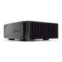
Tip: Use the factory-default 0 dB setting with
Benchmark's AHB2 power amplifier. When
directly driving most other power amplifiers
(or powered speakers), start with the 10 dB
pad setting. If necessary, change the pads so
that normal listening levels are achieved
when the VOLUME control is between the 11
o’clock and 3 o'clock positions.
When the output pads are enabled, the
output impedance changes slightly, and the
maximum recommended XLR cable length is
reduced as shown in Table 1. The table
assumes a cable capacitance of 32 pF/foot
and a maximum allowable loss of 0.1 dB at 20
kHz.
Table 1 - Cable Drive Capability
Balanced Output Drive Capability:
Attenuator Output Maximum Loss in dB
Setting (dB) Impedance Cable (ft) at 20 kHz
Unbalanced Output Drive Capability:
Output Maximum Loss in dB
Impedance Cable (ft) at 20 kHz