Instruction Manual for DAC3 HGC and DAC3 L with 2.X Firmware Page 11
Front Panel Displays
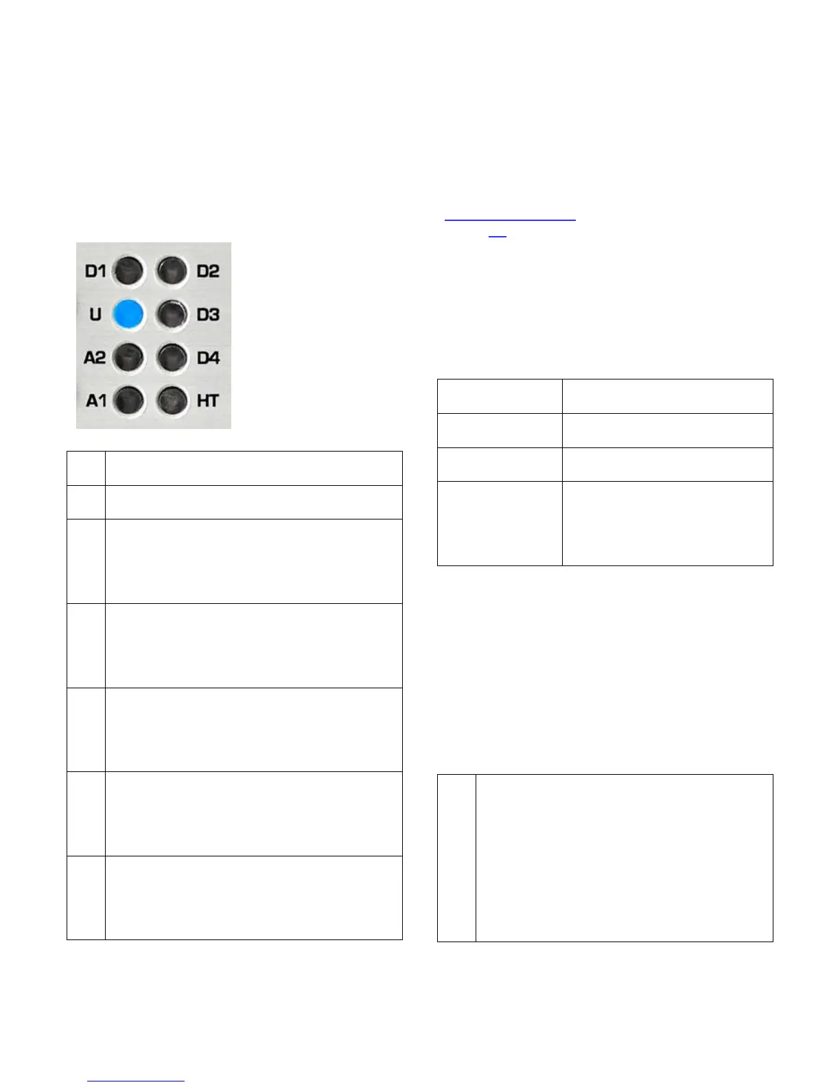
There are sixteen status indicator lights on
the front panel. At least one light will be
illuminated whenever power is on.
Input Indicators
The input indicators
show which input is
selected.
A flashing light
indicates an error on
a digital input.
The HT light shows
that HT mode is
active.
A solid blue light indicates that analog
input A1 is selected.
A solid blue light indicates that analog
input A2 is selected.
A solid blue light indicates that the USB
input is selected and operating normally.
A blinking blue light indicates that the
input is selected but a connection to a
computer has not been established.
A solid blue light indicates that optical
input D1 is selected and operating
normally. A blinking blue light indicates
that the input is selected but audio data
A solid blue light indicates that optical
input D2 is selected and operating
normally. A blinking blue light indicates
that the input is selected but audio data
A solid blue light indicates that coaxial
input D3 is selected and operating
normally. A blinking blue light indicates
that the input is selected but audio data
A solid blue light indicates that coaxial
input D4 is selected and operating
normally. A blinking blue light indicates
that the input is selected but audio data
Note: D4 cannot be selected if the Digital
Pass Through function is enabled.
Instructions for configuring this jumper-
selected function can be found in the
Internal Settings
section of this manual
(Page 30).
Input Error Codes
The input indicators flash when errors are
present on the selected digital input. There
are no error indications for analog inputs. Use
the following table to diagnose the problem:
No digital signal (output
muted)
Data transmission errors or
Non-PCM (output muted)
Non-audio data is being
received (output muted)
flashes
occurring, converter may be
interpolating to replace
invalid samples, check the
Tip: Common causes of input errors:
• Disconnected or faulty cable
• Use of excessively long digital cables
• Use of analog cables for digital signals
• Use of optical cables for sample rates
exceeding 96 kHz
• Incompatible data type (AC3, ADAT, etc.)
• Non-audio data is being received
HT Indicator
A solid light indicates that the HT mode
is active on the selected input and the
volume control is in the factory
calibrated position (near full clockwise).
A blinking light indicates that the HT
mode is active but the volume control
has not yet reached its calibrated
position. The HT light and DIM/MUTE
light will blink together if the unit is
muted while HT mode is active.