Instruction Manual for DAC3 HGC and DAC3 L with 2.X Firmware Page 28
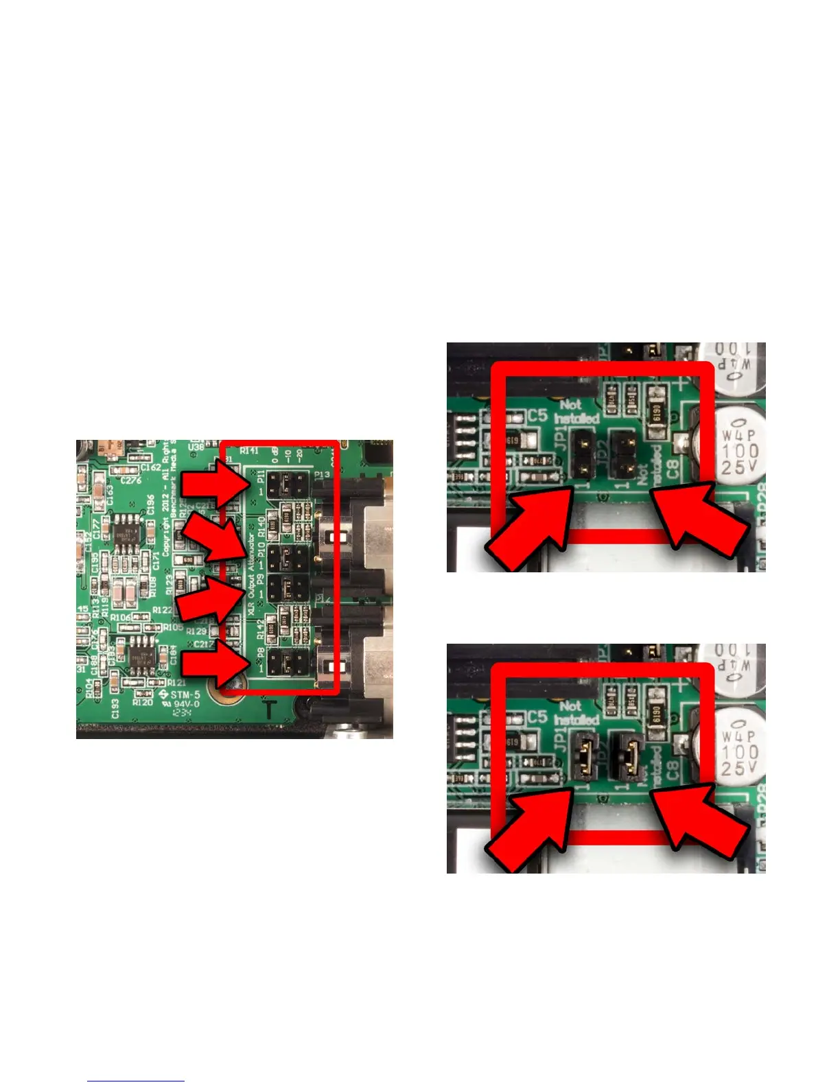
XLR Output Pad Jumpers
Four jumpers on four 6-pin headers (P8, P9,
P10, and P11) allow selection of the output
level at the XLR jacks. The jumpers are
properly configured if a normal playback level
is achieved when the VOLUME control is set
above the 11 o'clock position.
One pair of 6-pin headers control the
attenuation at each XLR jack as follows:
• 0 dB - (Attenuator disabled) – (Jumper
plug between pins 1 and 2 of each
header) - Factory Default
• -10 dB – (Jumper plug between pins 3
and 4 of each header)
• -20 dB – (Jumper plug between pins 5
and 6 of each header)
Figure 1 - Attenuators set to -10 dB
Headphone Switch Configuration
(DAC3 HGC only)
The left-hand headphone jack is equipped
with a switch that will mute the analog
outputs when a headphone plug is inserted.
The right-hand headphone jack does not have
a mute switch. In most cases it is convenient
to have one jack that mutes the outputs and
one that does not mute the outputs. If your
requirements are different the HEADPHONE
SWITCH can be defeated.
Headphone Switch Disable
The HEADPHONE SWITCH on the left-hand
headphone jack can be defeated by adding
jumpers at JP1 and JP2.
• HEADPHONE SWITCH enabled (no
jumpers at JP1 or JP2) - Factory Default
• HEADPHONE SWITCH disabled (jumpers
installed at JP1 and JP2)
Figure 2 - Headphone Switch Enabled
(Factory Default)
Figure 3 - Headphone Switch Disabled