MK2430_D00129_01_Q_DEEN/01.2024 5
COMTRAXX® MK2430
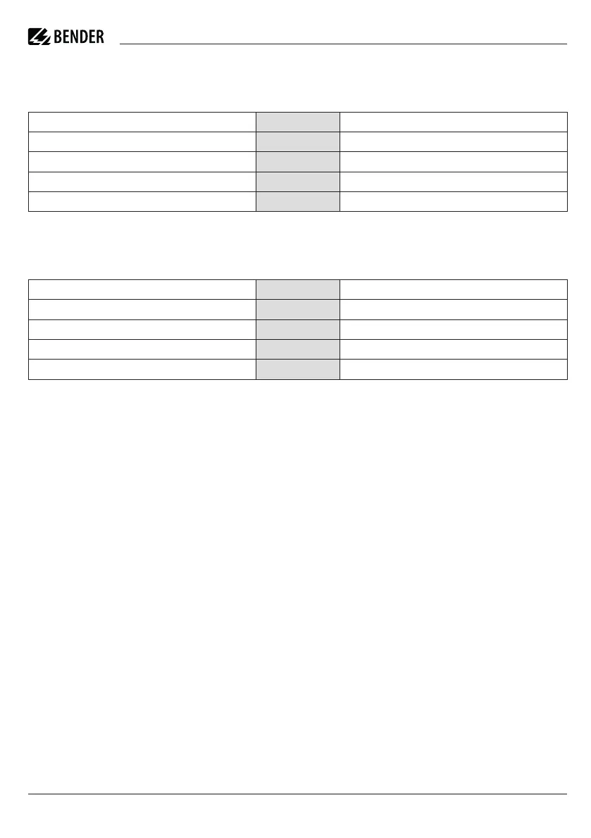
Connection assignment MK2430-12
The MK2430-12 features only one terminal strip as it
receives all messages via the BMS bus.
Connection assignment MK2430-11
The MK2430-11 provides additional terminal strips for
the 12 digital inputs and one optional relay output.
Commissioning
Check:
1. Does the MK2430 use the correct supply voltage?
2. Are all connections wired correctly?
3. Are terminating resistors for the BMS bus installed
correctly and switched on?
4. Are all devices in the system up to date?
5. Switch the supply voltage on. Measure the supply
voltage at the terminals U2, V2 (if the supply voltage
is too low, use another power supply unit).
Fix the MK2430 in the enclosure. Open the main menu
(press the “Menu” button for 2 seconds). In menu “4.
Settings”:
6. Set language
7. Set the BMS bus address.
8. Set the alarm addresses and system numbers.
9. Set the test addresses and ISOMETER® types.
10. Set time/date
All the basic settings can be carried out via the menu.
Further settings (e.g. individual alarm texts) can be carried
out via the TMK-SET software.
Anschlussbelegung MK2430-12
MK2430-12 enthält nur eine Klemmleiste, da sie alle
Meldungen über BMS-Bus erhält.
Versorgungsspannung U
s
U2, V2 Supply voltage U
s
USB-Anschluss. Kabel: Typ A Stecker auf Typ B Stecker. USB USB connection. Cable: Type A plug on type B plug.
Schirm des BMS-Busses und der USB-Schnittstelle. S BMS bus and USB interface shield.
BMS-Bus A, B BMS bus
BMS-Bus-Abschlusswiderstand, schaltbar Term BMS bus terminating resistor, switchable
Anschlussbelegung MK2430-11
MK2430-11 enthält zusätzliche Klemmleisten für die 12
digitalen Eingänge und einen optionalen Relaisausgang.
Digitale Eingänge 1…12 IN1…12 Digital inputs 1…12
gemeinsamer Anschluss „0“ für dig. Eingänge 1…4 0 (IN1…4) common connection “0” for the digital inputs 1…4
gemeinsamer Anschluss „0“ für dig. Eingänge 5…8 0 (IN5…8) common connection “0” for the digital inputs 5…8
gemeinsamer Anschluss „0“ für dig. Eingänge 9…12 0 (IN9…12) common connection “0” for the digital inputs 9…12
Relaisausgang (Option) 21, 22, 24 Relay output (option)
Inbetriebnahme
Prüfen Sie:
1. Ist Versorgungsspannung für MK2430 geeignet?
2. Sind alle Anschlüsse richtig verdrahtet?
3. Sind die Abschlusswiderstände für den BMS-Bus
richtig eingebaut bzw. eingeschaltet?
4. Sind alle Geräte im System auf aktuellem Stand?
5. Schalten Sie die Versorgungsspannung ein. Messen
Sie die Versorgungsspannung an den Klemmen U2,
V2 (falls zu niedrig, anderes Netzteil verwenden).
MK2430 im Gehäuse befestigen. Dann Hauptmenü öff-
nen (Taste „Menu“ 2 Sekunden lang drücken). Im Menü
„4. Einstellungen“:
6. Sprache einstellen
7. BMS-Busadresse einstellen
8. Alarmadressen und Systemnummern einstellen
9. Testadressen und ISOMETER®-Typen einstellen
10. Uhr/Datum einstellen
Über das Menü können alle grundlegenden Einstellungen
durchgeführt werden. Über die Software TMK-SET können
weitergehende Einstellungen (wie z. B. individuelle
Meldetexte) vorgenommen werden.

 Loading...


