4 MK2430_D00129_01_Q_DEEN/01.2024
COMTRAXX® MK2430
al support. They are needed in particular if the
MK2430 is to be fixed into an existing flush-mount-
ing enclosure (e.g. MK2418) which is not intended
for snap-on mounting (see MK2430 manual).
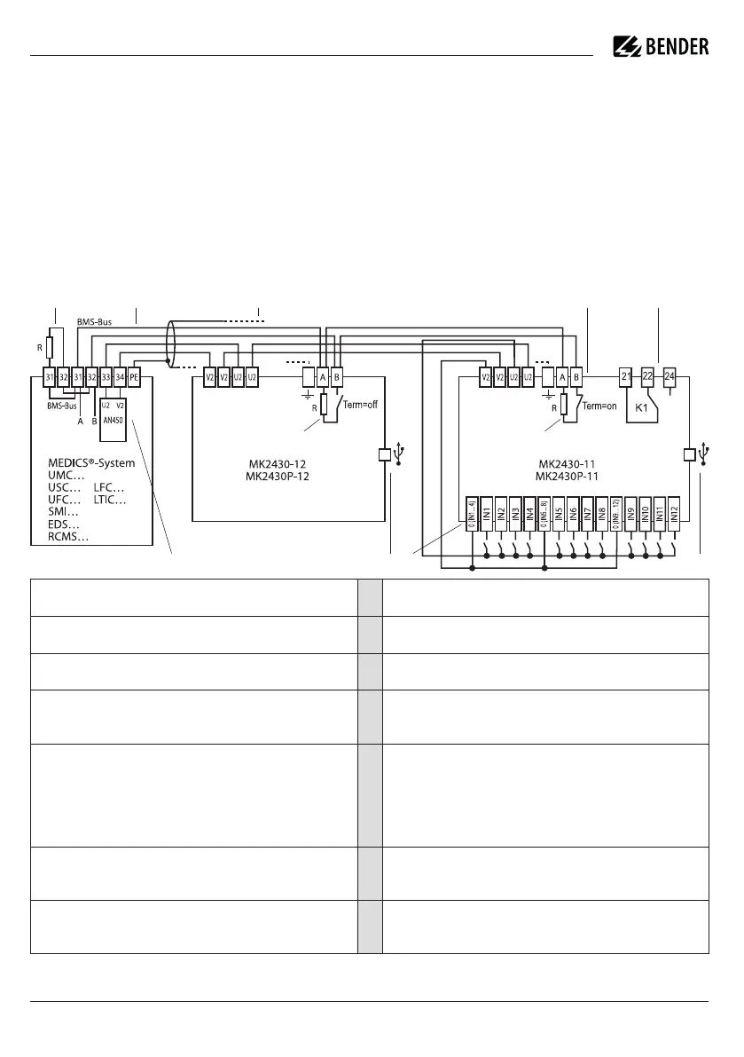
Connection example
I
Caution! Make sure that the power supply of the
MK2430 is isolated from earth (PE) (safety ex-
tra-low voltage SELV). If this is not taken into
consideration and if a PC is connected to the USB
interface, the MK 2430 device and the PC may be
damaged.
* Devices without BMS bus connection, but with test input (e.g. ISOMETER®)
dere benötigt, wenn MK2430 in bestehende Unter-
putzgehäuse (z. B. MK2418) eingebaut werden
sollen, die nicht für Schnappbefestigung vorgese-
hen sind (siehe Handbuch MK2430).
Anschlussbeispiel
I
VorsiCht! Stellen Sie sicher, dass die
Spannungsversorgung der MK2430 gegen PE iso-
liert ist (Sicherheits kleinspannung SELV). Wird
dies nicht beachtet und ein PC an die USB-
Schnittstelle angeschlossen, so drohen
Sachschäden an der MK2430 und dem PC.
Abschlusswiderstand BMS-Bus (R = 120 Ω), in der MK2430 über DIP-
Schalter zuschaltbar
1
Terminating resistor BMS bus (R = 120Ω), can be connected via DIP
switch on the MK2430.
Anschluss BMS-Bus (Bender-Messgeräte-Schnittstelle) zur Kommunika-
tion mit anderen Bender-Geräten
2
BMS bus connection (Bender Measuring Device Interface) for communi-
cation with other Bender devices
Netzteil im MEDICS®-Modul, ausreichend für die Versorgung von max.
drei MK2430
3
Power supply unit in the MEDICS® module, sufficient to supply a maxi-
mum of three MK2430s
Leitung zwischen MEDICS®-Modul und MK2430. Beachten Sie bei der
Versorgung der MK2430 durch das Netzteil AN450 bzw. AN410 in den
MEDICS®-Modulen die zulässigen Leitungslängen und Querschnitte.
4
Cable between the MEDICS® module and MK2430. Please observe the
permissible cable lengths and cross sections when using the AN450 or
AN410 power supply units in MEDICS® modules.
Digitale Eingänge: Die digitalen Eingänge können durch eine interne oder ex-
terne Spannung und potentialfreie Kontakte angesteuert werden. Werden
die Eingänge über eine externe Spannung angesteuert, wird der gemeinsa
-
me 0(-) auf die Klemme „0“ gelegt und das 1(+)-Signal auf den jeweiligen
Eingang IN1… 12. In diesem Fall entfallen die Verbindungen zwischen den
Klemmen 0 und V2, die gemeinsamen Verbindungen und U2.
5
Digital inputs: The digital inputs may be activated either via internal or
external voltage or potential-free contacts. If the inputs are activated via
an external voltage, the common 0(-) is applied to terminal “0” and the
1(+) signal to the relevant input IN1…12. In this case, the connections
between terminals 0 and V2, and the common connections and U2 are
not required.
USB-Schnittstelle: Dient zum Anschluss eines PCs. Mit der PC-Software
TMK-SET wird die MK2430 programmiert. Mit der PC-Software TMK-History
wird der Historienspeicher der MK2430 ausgelesen.
6
USB interface: For PC connection. The TMK-SET PC software is used to
program the MK2430. You can use the PC software TMK-HISTORY to read
out the MK2430 history memory.
Nur MK2430-11
Relaisausgang: Programmierbarer Kontakt für Gerätefehler, Test zugeordne-
ter Geräte*, Geräteausfall und Sammel-Alarmmeldung
7
MK2430-11 only:
Relay output: Programmable contact for device errors, test of assigned
devices*, device failure and common alarm message.
* Geräte ohne BMS-Bus-Anschluss, aber mit Test-Eingang (z. B. ISOMETER®)
ATICS. . .
isoMED. . .
1 1
1 12
3 5 6
7
6
4