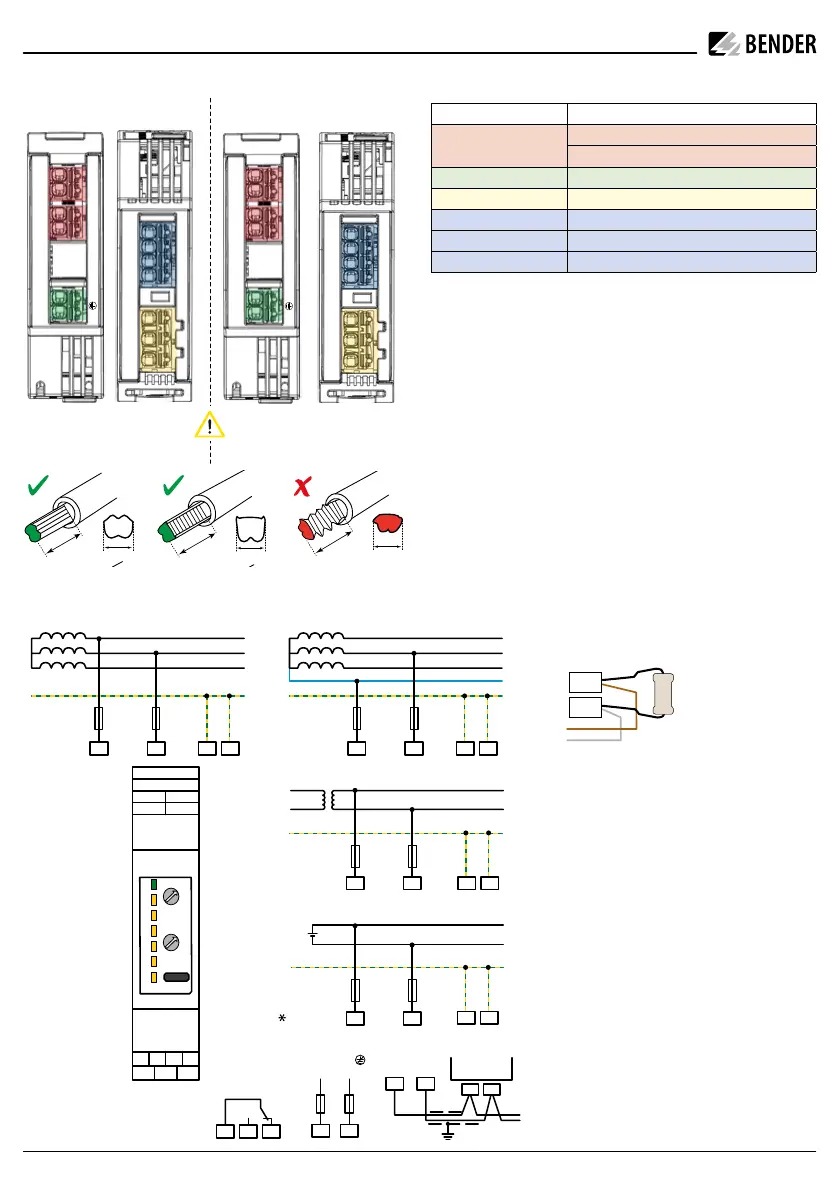
Anschluss / Connection
3AC 3(N)AC
AC
DC
L2
L3
PE
L1 L2 KE E
2A 2A
COM465IP
RS-485
J-Y(St)Y 2x0,6
A B
A B
11 14 12
+
-
+
-
2A 2A
L2
L3
N
PE
L1 L2 KE E
2A 2A
2A 2A
2A 2A
L1
L2
PE
KE E
L1 L2
L+
L-
PE
KE E
L1 L2
DC 24 V
L1
L2
E KE
11 14 12
BA-+
i
Bei mehr als 16 Bus-Teilnehmern der
Gerätevariante iso415R-2 ist die Schnitt-
stelle berührungssicher auszuführen,
weil der max. zulässige Gesamt-Ableit-
strom von 0,5 mA überschritten werden
kann.
i
If there are more than 16 bus devices of
the iso415R-2 device variant, the inter-
face must be designed to be touchproof,
because the maximum discharge current
of 0.5 mA could be exceeded.
i
* Achtung! Durch Kontaktströme in ei-
nem hohen Bereich wird die Hartvergol-
dung der Relaiskontakte beschädigt.
Beschädigte Kontakte verhindern dann,
dass das Relais bei niedrigen Kontakt-
strömen korrekt schaltet.
i
* Attention! High contact currents dam-
age the hard gold plating of the relay
contacts. Damaged contacts prevent the
relay from switching correctly at low
contact currents.
I
Vorsicht! Kurzschluss. Bei direktem Einschub fein-
drähtiger Leitungen in die Push-In-Klemmen kön-
nen gespleißte Drähte einen Kurzschluss verursa-
chen. Verwenden Sie Aderendhülsen.
I
caution! Short circuit. When finely stranded cables
are inserted directly into the push-in terminals,
spliced wires can cause a short circuit. Use ferrules.
i
Nur Aderendhülsen 0,25 - 1,5 mm² verwenden.
Ab 0,75 mm² nur Crimpzange (ähnlich CRIMPFOX 6
/ Weidmüller PZ6/PZ6/5) verwenden.
Für UL-Anwend. 60/75 °C CU-Leitungen verwenden.
i
Use ferrules 0.25 - 1.5 mm² only. From 0.75 mm², use
only crimping pliers (similar to CRIMPFOX 6 /
Weidmüller PZ6/PZ6/5)
.
For UL applications use 60/75 °C copper lines only.
iso415R-2
8
1.5
8
1.5
< 8
Anschluss / Terminal Verbindung / Connection
L1, L2
iso415R-2
Netznennspannung U
n
/ Nom. System voltage U
n
U
n
= U
s
E, KE Erde, Kontrollerde / Ground
11, 14, 12 Alarmrelais K1 / Alarm relay K1
iso415R-24: + / – U
s
: DC, + 24 V erdfrei / ungrounded
iso415R-2:
.
/
.
Ohne Funktion / Without function
COM A / B RS-485 Schnittstelle / RS-485 Interface
A
B
.
.
14
12
11
COM
K1
A
B
+
–
14
12
11
24 V
COM
K1
iso415R-24
KE
E
L1
L2
U
n
Terminierung RS-485 erstes und letztes Gerät
Termination RS-485 first and last device
B
A
120 Ω
< 0.25 W
U
s
: DC 24 V erdfrei / ungrounded
U
n
=
U
s
: AC/DC 100…240 V
KE
E
L1
L2
U
n
= U
s
2 iso415R_D00401_03_Q_DEEN / 07X.2022
ISOMETER® iso415R