8 isoCHA425HV_D00404_05_Q_DEEN / 11.2023
ISOMETER® isoCHA425HV + AGH420-1/AGH421-1
Commissioning
1. Check that the ISOMETER® is properly connected to
the system to be monitored.
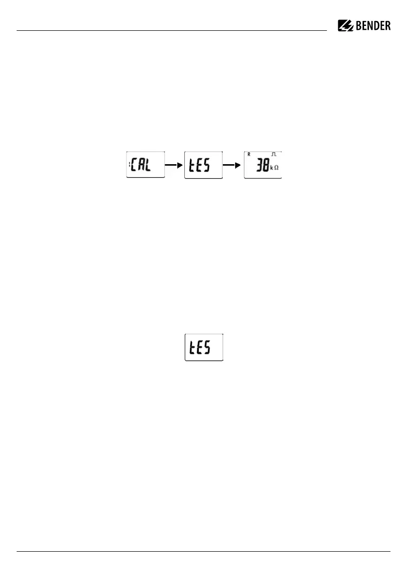
2. Connect the supply voltage U
s
to the ISOMETER®.
The device carries out a calibration, a self test and
adjusts itself to the IT system to be monitored. When
high system leakage capacitances are involved, this
procedure may take up to 4 min. The standard display
then appears showing the present insulation resis-
tance, e.g.:
The pulse symbol signals an error-free update of the
resistance and capacitance measuring values. If the
measuring value cannot be updated due to distur-
bances, the pulse symbol will be blanked.
3. Starting a manual self test by pressing the test but-
ton „T“. Whilst the test button is pressed and held
down, all display elements available for this device
are shown. During the test, the „tES“ symbol flashes.
Any internal malfunctions detected are shown on the
display as error codes. The alarm relays are not che-
cked during the test (factory setting). The setting can
be changed in the „out“ menu, so that the relays
switch into the alarm state during the manual self
test.
4. Check factory setting for suitability. Are the settings
suitable for the monitored installation?
5. Check the function using a genuine insulation fault.
Check the ISOMETER® in the system being monitored
against earth, e.g. via a suitable resistance.
Inbetriebnahme
1. Prüfen auf korrekten Anschluss des ISOMETER®s an
das zu überwachende Netz.
2. Versorgungsspannung U
s
für ISOMETER® zuschal-
ten. Das Gerät führt eine Kalibrierung, einen Selbst-
test und eine Justierung auf das zu überwachende
IT-Netz durch. Dieser Ablauf kann bei großen Netzab-
leitkapazitäten bis zu 4 min dauern, danach wird der
aktuelle Isolationswiderstand als Standardanzeige
eingeblendet, z. B.:
Das Pulssymbol signalisiert eine störungsfreie Aktua-
lisierung der Widerstands- und Kapazitätsmesswerte.
Falls durch Störungen der Messwert nicht aktualisiert
werden kann, wird das Pulssymbol ausgeblendet.
3. Starten eines manuellen Selbsttests durch Drücken
der Test-Taste „T“. Während des Drückens der Taste
(> 1,5 s) werden alle für dieses Gerät verfügbaren
Display-Elemente angezeigt. Für die Dauer des Tests
blinkt der Schriftzug „tES“. Ermittelte Funktionsstö-
rungen werden als Fehlercode angezeigt. Die Alarm-
relais werden dabei nicht geprüft (Werkseinstellung).
Im Menü „out“ kann die Einstellung so geändert wer-
den, dass beim manuellen Selbsttest die Relais in den
Alarmzustand wechseln.
4. Werkseinstellung auf Eignung prüfen. Sind die Ein-
stellungen für die überwachte Anlage geeignet?
5. Funktion mit einem echten Isolationsfehler prüfen.
Das ISOMETER® am überwachten Netz ist z. B. mit ei-
nem dafür geeigneten Widerstand gegen Erde zu
prüfen.