1515
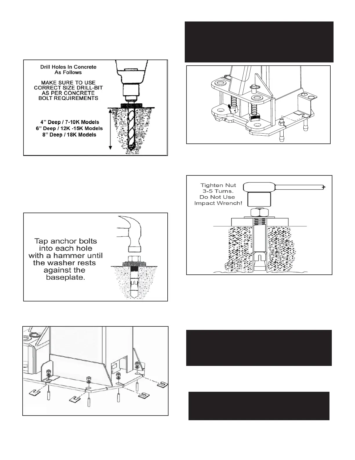
2. Using the baseplate on the POWER SIDE post as a
guide, drill each anchor hole in the concrete (approximately
4” deep for 10K models and 6” deep for 12K and 15K; 8” for
18K models) using a rotary hammer drill and 3/4” concrete
drill-bit. To ensure full holding power, do not ream the hole
or allow the drill to wobble. (See Fig. 5.1)
3. After drilling, remove dust thoroughly from each hole
making certain that the posts remain aligned with the
chalk line.
4. Assemble the washers and nuts on the anchors then
tap into each hole with a hammer until the washer rests
against the base plate. If shimming is required be sure
that enough threads are left exposed. (See Fig. 5.2)
5. If shimming is required, insert the shims as necessary
under the base plate so that when the anchor bolts are
tightened, the posts will be plumb. (See Fig. 5.3)
6. If installing the optional foot guards, place foot guards
on left and right side as shown. (See Fig 5.4)
7. With the foot guards, shims and anchor bolts in place,
tighten by securing the nut to the base then turning 3-5 full
turns clockwise (90 ft-lbs.). DO NOT use an impact wrench
for this procedure. (See Fig. 5.5)
STEP 6
(Installing the OFF SIDE post)
1. Position the OFF SIDE post at the designated chalk
locations and secure post to oor following the same proce-
dures as outlined in STEP 5; Paragraphs 1-6.
STEP 7
(Mounting the Overhead Assembly)
1. Remove all of the equalizer cable sheaves in prepara-
tion for the installation of the Overhead Assembly.
Fig 5.1
Fig 5.2
Fig 5.3
Fig 5.4
Fig 5.5
NOTE:
TO EASE THE INSTALLATION OF THE OVERHEAD
ASSEMBLY, IT HELPS TO KEEP THE ANCHOR BOLTS
LOOSE ON ONE OF THE POSTS UNTIL THE OVER-
HEAD ASSEMBLY IS MOUNTED.
NOTE:
IN ORDER TO ROUTE THE EQUALIZER CABLES
THE SHEAVES MUST BE REMOVED.
NOTE:
TO EASE INSTALLATION OF THE OVERHEAD
ASSEMBLY, IT HELPS TO KEEP THE ANCHOR
BOLTS LOOSE ON ONE OF THE POSTS UNTIL THE
OVERHEAD ASSEMBLY IS MOUNTED.