32
120001 Rev K 1-19-18
The 3700 Series can operate in two different modes, Console or Stand Alone, which must also be
defined by jumper settings on the CPU board:
Stand Alone Mode -Stand Alone mode allows the 3700 Series to operate without being connected to a
console or control device. In this mode, when the handle is turned “on” the dispenser authorizes itself.
Console Mode - Console mode allows the 3700 Series to communicate with compatible consoles or
control devices using a RS485 communication data loop. Also, the dispenser is also set for Console
mode when operating in mechanical mode with a Pulse Output board to a Fleet System. See below.
Mechanical Mode - Mechanical mode allows the 3700 Series to imitate a mechanical pump and
interface to a Fleet System. There is no actual “mechanical mode” to select. For this type of interface,
a separate “pulse output” board must be ordered with the system and the Console mode must be
selected. So, to put the system into “Mechanical Mode” install a Pulse Output Board and select the
Console Mode with the jumper. The field wires between the Fleet System and the dispenser
would be connected to the Pulse Output Board. This board would be used to output pulse data, handle
switch status information and would receive authorization signals from the Fleet System. When setting
the system up to imitate a mechanical dispenser, select CONSOLE mode. See the following section.
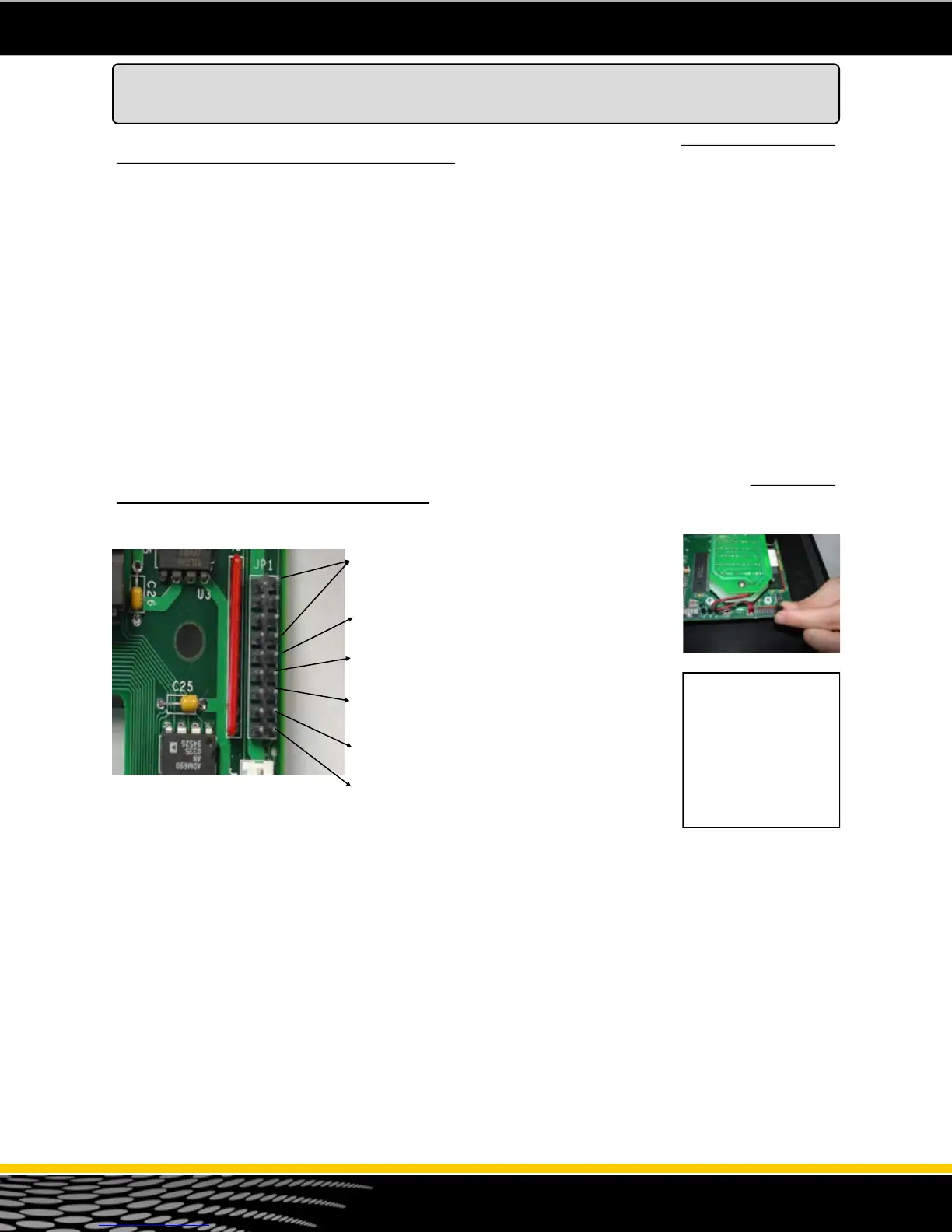
The 3700 series dispensers are programmed using “jumpers” or “shunts”. The jumper header JP1 is a
9 position header and is located on the top right corner on the back of the CPU/Board. This jumper
header is used to program the dispenser (see figure 21). Jumper configuration changes may be
required on the CPU circuit board at the site. See the chart below for a quick reference of what the
jumpers do. See the next page for an explanation of each jumper setting.
JP1-1 through JP1-4 - Fueling Point Address .
See Next Page.
JP1-5 - Console or Stand Alone Mode
JP1-6 - Suction Pump Motor Delay
JP1-7 - Leak Detector Pre-charge
JP1-8 - Imperial Gallons
JP1-9 - Units
Figure 21 - CPU Jumpers on JP1
CPU Board Jumper Configuration
Console Mode - Setting Jumpers
The 3700 Series is shipped from the factory configured for the console mode of operation. In the
“Console” mode, the 3700 electronic commercial dispenser can communicate with any console that can
communicate using RS485 communication. It is also set for Console when using the mechanical
interface pulse output board. When in the “Console” mode, after the handle is lifted, the dispenser must
receive the “authorization” command from the console or controlling device before the dispenser resets
and begins the sale.
Jumper Header JP1 is a 9 position jumper header (see figure 22). Position 5 is for setting the dispenser
in the Console or Stand Alone mode. Placing the jumper across the pins on position 5 puts the
dispenser in Console mode.
This jumper configures the CPU for RS485 output on TS1 (Field wire connection to the Console).
TS1-7 = DATA (–)
TS1- 6 = DATA (Common)
TS1 - 5 = Data (+)
Figure 22 - JP1 Position
Jumper Header JP1 is
located on the top right of
the back of the CPU /
Control board. This board
is mounted to the upper
door. It has 9 positions.
Jumpers should be set
with dispenser power off.
The jumper settings are
only read on “power up”.