77
120001 Rev K 1-19-18
Notes to Installer: System Operation -
If the dispenser was ordered with the “Pulse
Output” function, one or two Pulse Output Boards
will be installed in the dispenser. One P.O.B.
(Pulse Output Board) can communicate with 2 CPU
boards.
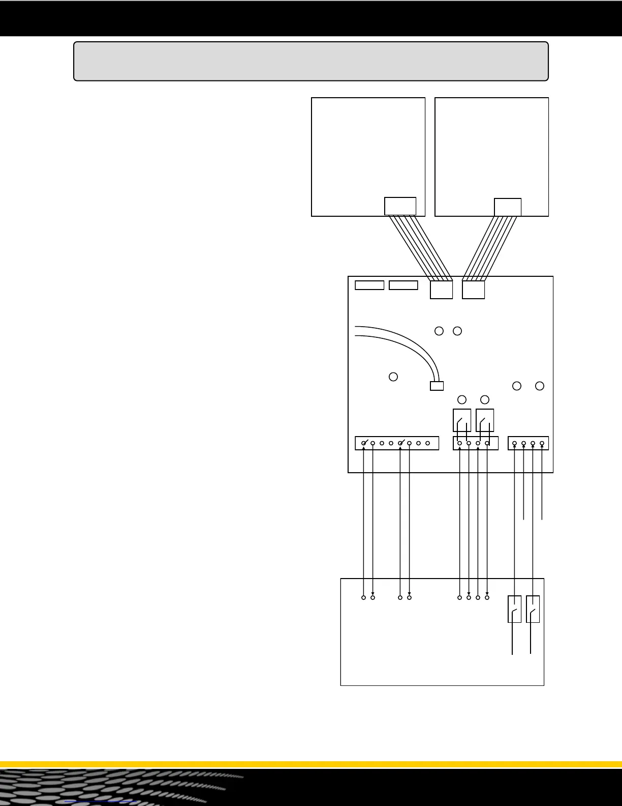
The pulse output board is field wired to the 3rd
party Fleet Control System as shown in figure 44.
The P.O.B. is mounted horizontally on top of the
Barrier Circuit (cover) inside the head of the
dispenser.
Pulse output - The dispenser emulates a
mechanical reed switch pulser. Pulse rates of 1:1,
10:1, 100:1 and 1000:1 are available. When wiring
the pulse channels to the 3rd party system, the
fleet system must be set up for a DC voltage. It
must provide +5 to +12 vdc for the pulse circuit.
Voltage is not provided by the dispenser pulse
output board. TS1 provides 4 pulse output
channels (2 pulse outputs to the 3rd party fleet
system and two channels to an electronic tank
gauge). All 4 of these circuits are identical.
Handle Circuit - The handle signal on the P.O.B.
is used to signal the Fleet System that the pump is
“In Use” The P.O.B. uses a dry contact (normally
open) relay type of circuit. Run two wires from the
Fleet System to TS2. When the dispenser handle is
lifted this relay will close. This should signal the
Fleet System that the pump is “In Use”. The handle
signal can be an A.C. voltage or D.C. voltage. This
drawing shows a D.C. voltage as an example.
Authorization Signal - The dispenser P.O.B.
requires an authorization signal from the Fleet
System to start a sale. Without this authorization
signal, the pump will never reset and the sale will
not begin. The Fleet System sends the
authorization signal in the form of 120 volt A.C.
signal to TS3 as shown in the diagram to the right.
When the P.O.B. receives the authorization signal
and the handle is lifted, and the dispenser is
programmed properly, the sale should begin.
Wiring to the Fleet System - Refer to the CD-
ROM provided with the dispenser. Bennett
provides various interface diagrams to many of the
popular fleet card systems. Always consult with the
manufacturer and read all product manuals for
additional information on installing the 3rd party
card system. Call Bennett Technical Support for
assistance at 1-800-423-6638.
Pulse Output
Board
Note 1 - The handle signal can be an A.C. voltage or a
D.C. voltage. This board only provides a switch relay.
CPU
Product 2
J8
CPU
Product 1
J1 J2
TS1 TS2 TS3
D 9 D 10
D 4 D 7
D 3 D 6
D 2
TEST LED
Pulse Output Side 1 (+)
Pulse Output Side 1 (-)
Pulse Output Side 2 (+)
Pulse Output Side 2 (-)
Authorization Side 1 (120 v)
(-) (+) (-) (+)
120 volt
120 volt
+12 vdc or 120 vac Handle Side 1
(Com)
(Com)
+12 vdc
+12 vdc
(Com)
(Com)
JP5 JP6 JP8 JP7
JP1 JP2
Red
Black
Test Cable
+12 vdc or 120 vac Handle Side 2
J8
Figure 44 - Pulse Output Diagram
Pulse Output Board (Optional)
Neutral
Neutral
Authorization Side 2 (120 v)