30
3000 Series Retail Operators Manual 108796 Rev C, 07/05
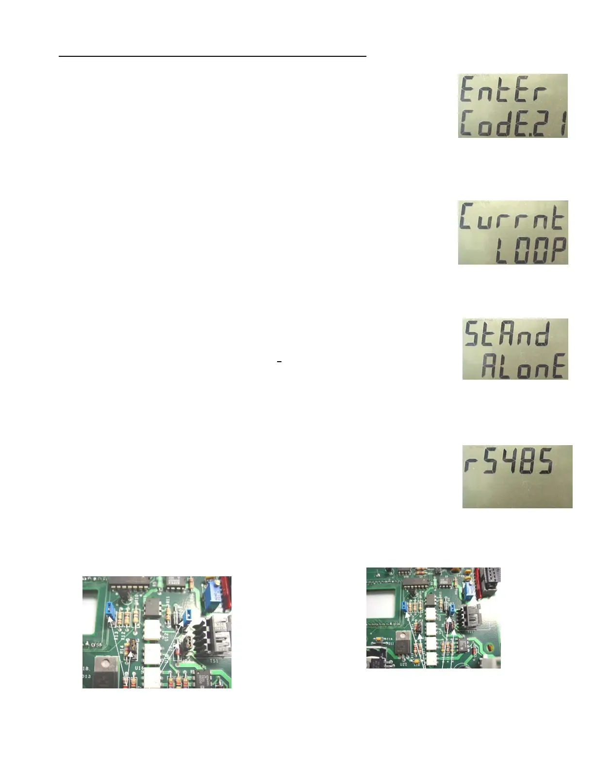
Menu Code 21 - How to Set the Dispenser Mode of Operation
This menu code allows the Manager to set the dispenser mode of operation. The options are:
• 0 - the Current Loop mode is active (this is the default) See Figure 2
• 1 - the Stand Alone option is active. See Figure 3.
• 2 - RS-485 for RS485 consoles OR mechanical interface to Fleet System. See Figure 4.
Note - Current Loop - Standard ( 2 wire per fueling point) current loop Bennett protocol to consoles that
support Bennett Current Loop Protocol. Example: Verifone Ruby. There are jumper setting that must be
checked on the CPU. See Below
Note - Stand Alone - Use the Stand Alone Mode when operating the dispenser without the use of a console
or control system. Stand Alone is also commonly used when starting up the dispenser for the first time to
test it.
Note - RS485 - Use the RS485 mode when using Pulse Output (mechanical interface) OR when connected
to a console that communicates using the simple Bennett RS485 Command Protocol. There are jumper
settings that must be checked on the CPU. See Below.
Use RS485 when connecting to a Fleet Management System. A simple protocol provides the FMS with the
pump status, pulses, volume sales amount and volume totals. The RS485 protocol will not accept price
changes.
An alternative method of interfacing to a fleet management system is via the optional dual pulse output
board instead of the RS485 protocol. Pulse output emulates the pulses of a Veeder-Root pulser commonly
used in mechanical dispensers for 10:1 or 100:1 pulse ratios.
One dual phase output board provides pulse output for 2
hoses. For example, a model 3812 twin pump
would require only one pulse output board. Additionally, the pulse output board has two channels per hose
so that pulses can be provided for both a Fleet Management System AND an Electronic Tank Gauge sys-
tem.
To select a different option in Menu Code 21, follow this procedure:
1. After the Manager’s Mode has been accessed, press the number 2 and 1, then the MODE button on the key-
pad. See Figure 1. The PPV display shows the dispenser is in Menu Code 21.
If the dispenser has not been programmed since it came from the factory, the Current Loop Mode appears in
the main display. This is the default setting. See Figure 2.
2. To change the setting, use the 0, 1, or 2 button on the keypad to enter a new option. See Figures 3 (Stand
Alone) and 4 (RS485).
NOTE: If an error is made, press the correct number. The new number replaces the error.
1. When the correct option number appears in the main display, press the ENTER button to save your setting.
2. Press the CANCEL button to exit this menu code.
Fig. 1
Fig. 2
Fig. 3
Fig. 4
Jumper Settings for Current Loop -
JP2, 3, 4, and 5 should be set to top 2
pins on all four jumpers..
Jumper Settings for RS485 - JP2, 3, 4,
and 5 should be set to bottom 2 pins
on all four jumpers.