32
3000 Series Retail Operators Manual 108796 Rev C, 07/05
Dual Product Dispenser
Dual Product Dispenser
A
d
d
r
e
s
s
o
Address o
Address o
Address o
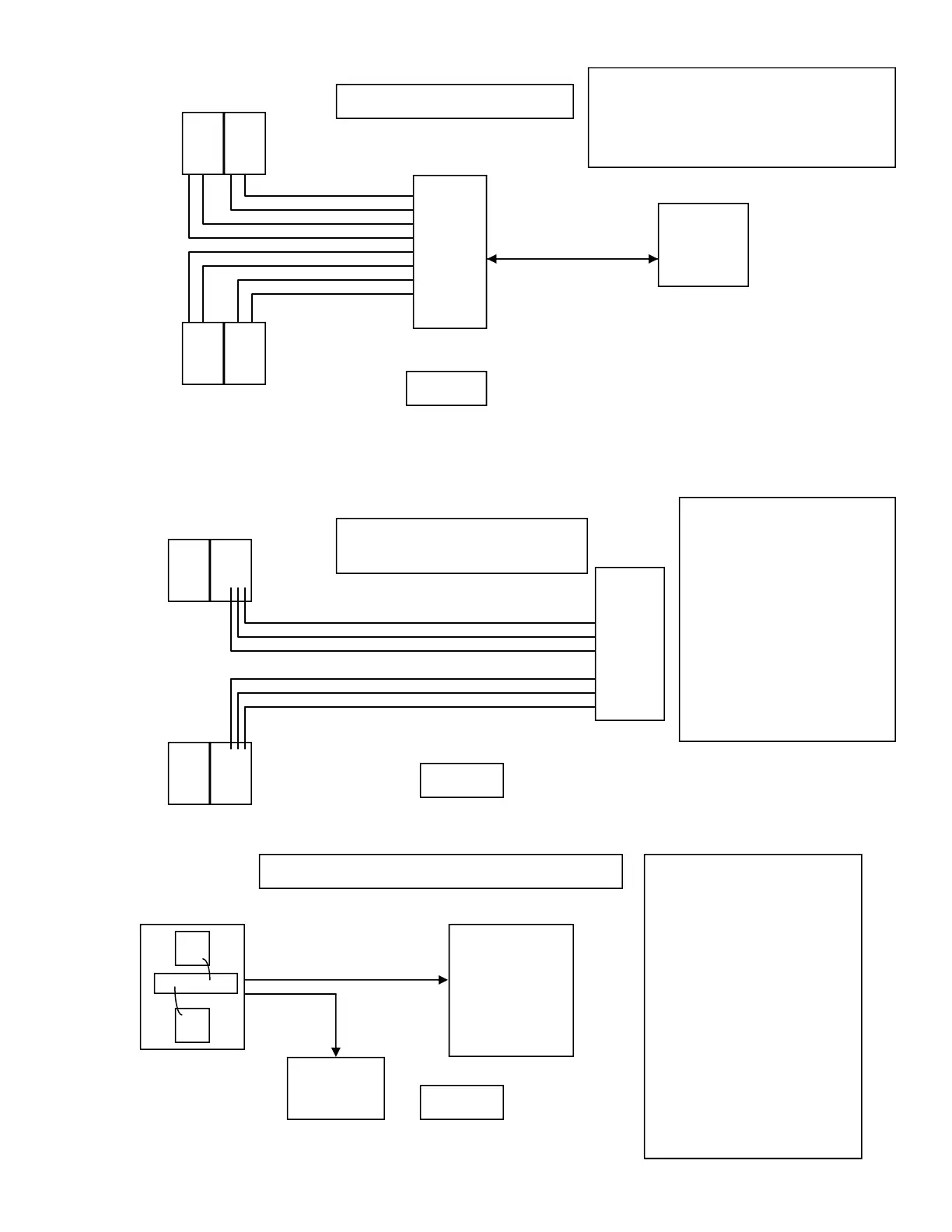
515 Box
Current Loop Communication
Current Loop is when you have 2 com wires running to
each Cpu and a model 515 box. Mode 21 is set to “Current
Loop” and Mode 22 (Dispenser Address) is set to 0 for each
CPU. The “address” is determined by where it is connected
in the 515 box.
Verifone
Console
Dual Product Dispenser
Dual Product Dispenser
Address 1
Address 4
Address 3
Address 2
(common)
(+)
(-)
(-)
(+)
(common)
RS485 Communication for
Fleet Management System
RS485 communication uses 3 wire to
the first cpu in the dispenser and daisy
chains to any other cup's in that same
dispenser. This is for Fleet Systems that
use RS485 communication. So, each
Cpu must be programmed with a unique
address in mode 22. In this case, each
cpu was programmed with a different
address so that the console knows
which one it is talking to. Single Cpu
dispenser address the CPU with 1.
A Dual Cpu dispenser you will address
side 1 with address 1 and side 2 with
address 2. A “Quad” or 4 Cpu dis-
penser will have addresses 1, 2, 3, and
4.
Side 1
Side 2
Cpu
Cpu
Pulse Output Bd.
Address 2 Address 1
Fleet System
Fleet System Communication - Pulse Output
As an alternative, with a Fleet System,
the dispenser has a Pulse Output board.
This board is field wired to the Fleet
System. This board also connects to up
to 2 Cpu’s in the dispenser. It talks to the
Cpu’s using RS485 communication.
Therfore, mode 21 should be set for
RS485. Also, when using RS485 you
must give each Cpu an address so that the
Pulse Output board knows which one it is
talking to. So, when using a Pulse output
board with a Fleet System, address side 1
with address 1 and side 2 with address 2
always. A Dual Cpu dispenser you will
address side 1 with address 1 and side 2
with address 2. A “Quad” or 4 Cpu dis-
penser will have addresses 1, 2, 3, and 4.
1&2 will be connected to the first pulse
output board and 3&4 will be connected
to the second pulse output board.
Figure 1
Figure 3
Figure 2
Dual Product Dispenser
RS485 Fleet System
Pulse Output
Pulse Output
Tank Monitor