Q7T3(AUO Panel) LCD Monitor Service Guide
Circuit Operation Theory
6
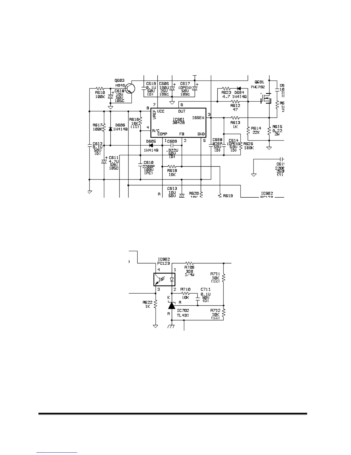
#5 PWM Controller
The current mode control IC UC3842B is used to control PWM. When the VCC terminal of it gets
16V, IC601 turns on. +5V will be set up at Pin8 through soft start circuit, which includes R617, C611,
D606 and D605. R616 and C610 generate a fixed frequency saw-tooth wave at Pin4.
Fig. 6
#6 Feedback circuit
PC123 is a photo-coupler and TL431 is a shunt regulation. They are used to detect the output
voltage change and be the primary and secondary isolation. When output voltage changes, the
feedback voltage will be compared and duty cycle will be decided to control the correct output
voltage. (See Fig.7)
Fig. 7
A-3.) Control board introduction:
The main parts of the control board are a push button, and a LED.
(a) Push button:
It’s a simple switch function, pressing it for “ON” to do the auto adjustment
function, releasing it for “OFF” to do nothing.
(c) LED:
It indicates the DPMS status of this LCD monitor; green light means DPMS on
(Normal operating condition). Amber light means DPMS off (Power off condition).
 Loading...