Q7T3-FP737S Dual function LCD Monitor Service Guide
Circuit Operation Theory
7
Confidential
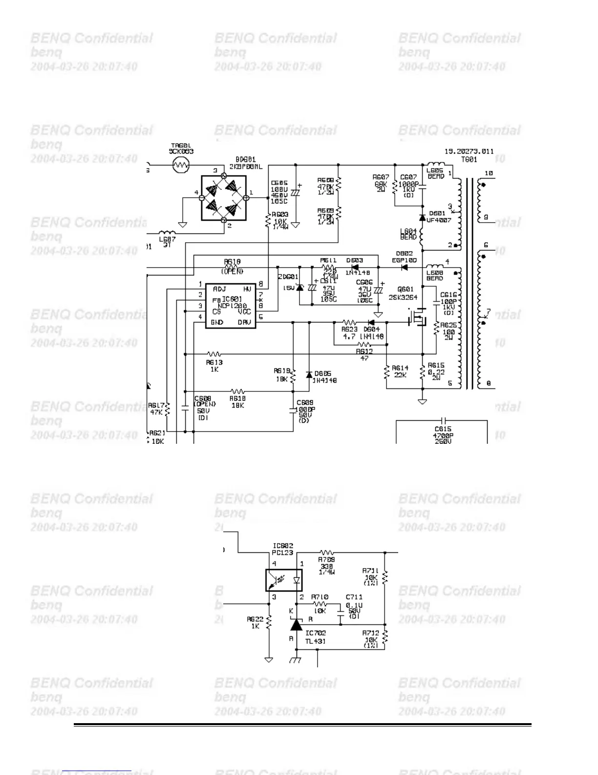
#5 PWM Controller
The PWM controller NCP1200A implements a standard current mode architecture. With an internal structure
operating at a fixed 40KHz. Where the switch time is dictated by the peak current set-point. When the current
set-point falls below a given value. The output power demand diminishes, the IC automatically enters the so-called
skip cycle mode and provides excellent efficiency.
Fig. 6
#6 Feedback circuit
PC123 is a photo-coupler and TL431 is a shunt regulation. They are used to detect the output voltage
change and be the primary and secondary isolation. When output voltage changes, the feedback voltage will
be compared and duty cycle will be decided to control the correct output voltage. (See Fig.7)
Fig. 7

 Loading...