EasyManua.ls Logo

BenQ Q7T3-FP737S User Manual

BenQ Q7T3-FP737S
140 pages
To Next Page IconTo Next Page
Page #1 background imageLoading...
Page #1 background image
Q7T3-FP737S Dual function LCD Monitor Service Guide
Alignment Procedure
1
Confidential
1. Alignment procedure (for function adjustment)
A. Preparation:
1. Setup input timing ICL-605, 32-Grays pattern.
2. Setup unit and keep it warm up at least 30 minutes.
B. Timing adjustment:
1. Enter factory setting area (press “ENTER”, “EXIT” and then press “SOFTPOWER”).
2. Check the settings to following values:
Contrast = 50
Brightness = 90
Volume = 30
OSD time = 20
Color = sRGB
Language = English
Then, turn off the monitor power.
3. Turn on power enter user area.
C. Color balance adjustment:
1. Enter factory setting area (press “ENTER”, “EXIT” and then press “SOFTPOWER”).
2. Setup input timing ICL-605 (1280*1024 75Hz), 5-MOSAIC pattern.(timing 202 pattern 42)
3. Press”I-key”,to enter window for whitebalance and burning mode.
4. Press “Whitebalance”, to Calibrate ADC.
5. Setup input timing ICL-605, 32 -Gray pattern.
6. Checking if the picture is no good, reject this monitor.
D. Color adjustment:
1. Setup input timing ICL-605, white pattern.
2. Measure color temperature by Minolta CA-110 (or equivalent equipment).
3. Alignment the color temperature Bluish, Reddish & sRGB. The color temperature
specification as follows:
X+- 0.283+(-) 0.03 White Balance
(Bluish, 9300K set on OSD)
Y+- 0.297+(-) 0.03
X+- 0. 326+(-) 0.03 White Balance
(Reddish, 5800K set on OSD)
Y+- 0. 342+(-) 0.03
X+- 0. 313+(-) 0.03 White Balance
(sRGB, 6500K set on OSD)
Y+- 0. 329 +(-) 0.03

Table of Contents

Question and Answer IconNeed help?

Do you have a question about the BenQ Q7T3-FP737S and is the answer not in the manual?
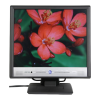
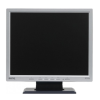
BenQ Q7T3-FP737S Specifications

General IconGeneral
Screen Size17 inches
Resolution1280 x 1024
Contrast Ratio500:1
Aspect Ratio5:4
Panel TypeTN
Viewing Angle130° vertical
Input ConnectorsVGA

Summary

Alignment Procedure

1. Alignment procedure (for function adjustment)

Detailed steps for monitor alignment and function adjustment.

A. Preparation

Steps to prepare for alignment procedures.

B. Timing adjustment

Procedure for adjusting display timing parameters.

C. Color balance adjustment

Steps for adjusting the monitor's color balance.

D. Color adjustment

Procedure for aligning color temperature.

E. Writing EDID file

Process for writing EDID files to EEPROM.

F. Command definition

Defines I2C commands for monitor control.

2. Dressing

Physical assembly steps for the monitor.

A. Check the 4 springs and 5 spacers on the BKT

Inspecting components on the bracket.

B. Connect 2 with 1 then connect to connector 3

Connecting internal cables and connectors.

C. Fix DVI BD with spacers

Securing the DVI board with spacers.

D. Place I/F BD and SPS BD in the BKT

Installing interface and power supply boards.

G. Screw D-SUB cover on the BKT

Securing the D-SUB cover.

H. Two gaskets at the bottom of BKT

Installing gaskets on the bracket.

I. Taping LVDS FFC on the panel

Securing the LVDS FFC cable.

J. Place BKT on the panel and fasten FFC with I/F BD

Mounting the bracket and connecting FFC.

K. Place an iron cover and screw it on BKT

Installing and securing an iron cover.

L. Two screws on panel right side

Fastening screws on the right side.

M. Two screws on panel left side

Fastening screws on the left side.

N. Paste aluminum tape on the backlight wire hole

Applying aluminum tape to a wire hole.

O. Spring on control board and fix CTRL BD on BZL

Attaching spring and control board.

P. Contorl board 9pin wire dressing

Routing the control board 9-pin wire.

Q. Screw up uppercase with 5 screw

Securing the upper case with screws.

R. Screw column with uppercase with 2 screw

Fastening screws on the column.

Engineering Specification

2. Operational Specification

Specifications for operating the monitor.

2.1 Environment

Environmental conditions for operation.

2.1.1 Temperature

Operating and storage temperature ranges.

2.1.2 Relative Humidity

Humidity limits for operation and storage.

2.1.3 Altitude

Altitude limits for operation and storage.

2.2 Transportation

Specifications for transporting the monitor.

2.2.1 Vibration Test (Package, Non-Operating)

Vibration test parameters for packaged units.

2.2.2 Drop Test (Package, Non-Operating)

Drop test specifications for packaged units.

2.3 Packing Configuration

Details on packing configurations.

2.3.1 Container Specification

Specifications for shipping containers.

2.4 Electrostatic Discharge Requirements

Electrostatic Discharge (ESD) compliance requirements.

2.5 Safety Requirements

Compliance with safety standards.

2.6 EMI Requirements

Electromagnetic Interference (EMI) compliance requirements.

2.7 Reliability

Reliability specifications, including MTBF.

3. Input / Output Signal Specification

Specifications for input/output signals.

3.1 Input Signal Requirements

Requirements for input video and sync signals.

3.2 Function

Functions of the monitor.

3.2.1 Support timing

Supported display timings and resolutions.

3.5 Power Supply Requirements

Input and output power specifications.

3.7 Panel optical Characteristics

Optical characteristics of the LCD panel.

4. Functional specification

All tests performed under standard conditions.

4.1 Display Quality

Specifications related to display quality.

5. Physical Specifications

Physical specifications of the monitor.

5.1 Physical Dimension & Appearance

Overall dimensions and appearance details.

6. Maintainability Specifications

Specifications for maintainability.

6.1 General & Requirements

General requirements for maintainability.

6.1.3 Repair & Calibration

Procedures for repair and calibration.

6.2 Mean Time to Repair

Mean Time To Repair (MTTR) for modules and components.

6.4 Equipment & Tools Required

Required equipment and tools for service.

Trouble Shooting Guide

1.No Display or display is unstable

Troubleshooting steps for no display or unstable image.

1.1 Interface Board

Troubleshooting steps for interface board issues.

2. BUTTON function

Troubleshooting steps for the button function.

2.1 Control Board

Troubleshooting steps for the control board.

3. OSD function

Troubleshooting steps for the On-Screen Display function.

4. Power Board

Troubleshooting steps for power board issues.

Circuit Operation Theory

I. Introduction

Overview of the LCD monitor's functionality.

II. Block diagram

Schematic showing the monitor's main components.

III. Circuit operation theory

Detailed explanation of circuit operations.

A.) HEAD

Details about the monitor's head section.

A-1.) Interface board diagram

Diagram of the interface board.

(a) Circuit operation theory

Explanation of the interface board's operation.

(b) IC introduction

Details on key ICs used on the interface board.

A-2.) Power board diagram

Block diagram of the power supply board.

A-3.) Control board introduction

Overview of the control board components.

A-4.) Inverter diagram

Block diagram of the inverter circuit.

Related product manuals