Q7T3(AUO Panel) LCD Monitor Service Guide
Circuit Operation Theory
3
Rapid-lock digital clock recovery system. It also support detect mode and DPMS control. MCU
control unit, it controls all the functions of this interface board, just like the OSD display setting,
the adjustable items, adjusted data storage, the external IIC communication, support DDC2B.
3.) EEPROM: We use 24C16 to store all the adjustable data and user settings.
4.) FLASH ROM: To stored the source code which is accessed by MCU to run program.
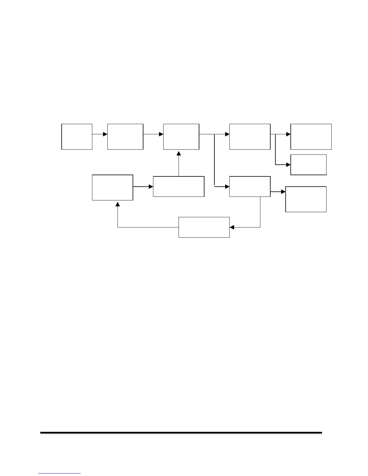
A-2.) Power board diagram:
Fig.1
#1 EMI Filter
This circuit (fig. 2) is designed to inhibit electrical and magnetic interference for meeting FCC,
VDE, VCCI standard requirements.
EMI Filter Rectifier and
filter
Isolation power
transformer
Rectifier and filter Audio Amp and
Pre-Amp
PWM controller
Switching element
Feedback Isolation
Inverter circuit
Rectifier and filter
LDO regulator
 Loading...