Contents
DESCRIPTION................................................................................................................................. 6
Warning .......................................................................................................................................................................6
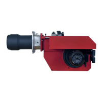
2-Stage ........................................................................................................................................................................ 7
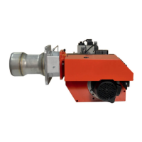
Modulating...................................................................................................................................................................8
TECHNICAL DATA ........................................................................................................................... 9
Dimensions .................................................................................................................................................................9
Output range .............................................................................................................................................................10
Working field............................................................................................................................................................. 11
SKELETON DIAGRAMS ...............................................................................................................12
2-stage or modulating burners................................................................................................................................12
MOUNTING OF THE BURNER.................................................................................................... 13
Inspection of gas assembly.....................................................................................................................................13
Adjustment of the position of the shrouded disc in the blast tube .......................................................................13
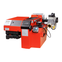
ELECTRIC EQUIPMENT .............................................................................................................. 14
Wiring diagram LGB22/LMG22/LME22 (BG550/BG650) 2-Stage............................................................................14
List of components LGB22/LMG22/LME22 (BG550/BG650) 2-Stage .....................................................................15
Function LGB22/LMG22/LME22 ................................................................................................................................15
Wiring diagram LMG22/LME22 (BG550/BG550LN/BG650) Modulating ..................................................................16
List of components LMG22/LME22 (BG550/BG550LN/BG650) Modulating ...........................................................17
Function LMG22/LME22 ............................................................................................................................................17
Wiring diagram LMG22 (BG550/BG550LN/BG650) Modulating with R316 ............................................................18
List of components LMG22 (BG550/BG550LN/BG650) Modulating with R316 ......................................................19
Function LMG22 ........................................................................................................................................................19
Control diagnosis under fault conditions and lockout indication..........................................................................20
Gas burner control: LGB ... ......................................................................................................................................20
Control diagnosis under fault conditions and lockout indication..........................................................................21
Gas burner control: LMG .........................................................................................................................................21
Control program when disruption; disruption display ...........................................................................................22
Gas burner control: LME.... ......................................................................................................................................22
Wiring diagram LFL1... (BG550/BG650) 2-Stage .....................................................................................................24
List of components LFL1... (BG550/BG650) 2-Stage ..............................................................................................25
Function LFL1... .........................................................................................................................................................25
Wiring diagram LFL1... (BG550/BG550LN/BG650) Modulating ...............................................................................26
List of components LFL1... (BG550/BG550LN/BG650) Modulating ........................................................................27
Function LFL1... .........................................................................................................................................................27
Wiring diagram LFL1... (BG550/BG550LN/BG650) Modulating with R316 .............................................................28
List of components LFL1... (BG550/BG550LN/BG650) Modulating with R316.......................................................29
Function LFL1... .........................................................................................................................................................29
Wiring diagram LFL1... (BG550/BG650) 2-Stage .....................................................................................................30
List of components LFL1... (BG550/BG650) 2-Stage ..............................................................................................31
Function LFL1... .........................................................................................................................................................31
Control programme under fault conditions and lockout indication LFL1.... ......................................................... 32
Technical data LFL1... ...............................................................................................................................................32
MEASURES AND CHECKS BEFORE START-UP ....................................................................... 33
2-Stage or modulating burners ...............................................................................................................................33
Inner assembly .........................................................................................................................................................34
Inner assembly BG 550LN........................................................................................................................................35
DETERMINATION OF GAS VOLUME FOR THE INSTALLATION ............................................. 36
Example how to calculate the gas volume (natural gas) ......................................................................................36
GAS SOLENOID VALVE MVD ....................................................................................................... 37
OPERATION AND ASSEMBLY INSTRUCTIONS ........................................................................ 38
Double solenoid valve Type DMV-D.../11 Type DMV-DLE.../11 ..................................................................................38
OPERATION AND ASSEMBLY INSTRUCTIONS ........................................................................ 41
Gas pressure regulator Type FRS ...........................................................................................................................41
MULTI-BLOC, MB-ZRDLE 405 - 420 B01 .................................................................................... 43
Flow adjustment 2-stage design .............................................................................................................................44
Adjustment of governor ...........................................................................................................................................44
Adjustment of start gas flow ...................................................................................................................................44