45
MULTI-BLOC, MB-VEF 412 - 425 B01
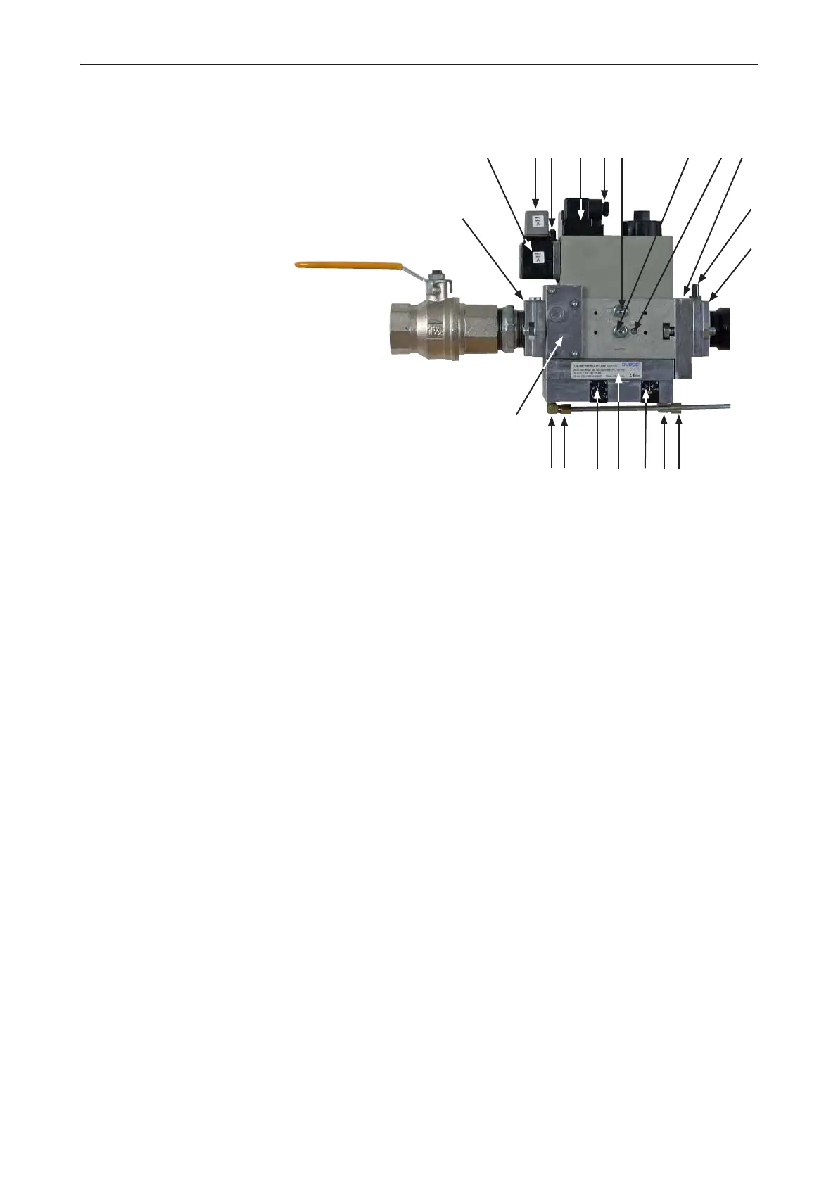
View
1. Electrical connection gas pressure switch mini
2. Electrical connection gas valve
3. Pressure switch mini
4. Flange connection inlet
5. Test point connection 1/8" before V
1
6. Filter (on Multi-Bloc 425 external filter)
7. Data plate
8. Connection 1/8" P
L
9. Adjustment screw V for ratio P
Br
: P
L
(max. load)
10. Test point connection 1/8" before V
1
(before governor)
11. Connection M4 for measurement of burner pressure after V
2
12. Adjustment screw for zero point adjustment N (min. load)
13. Test point connection 1/8" P
F
14. Test point connection 1/8" P
Br
(after V
2
burner)
15. Flange connection, outlet
16. Test point connection 1/8" P
a
before V
2
(after governor)
17. Indication of V
1
and V
2
in operation (not standard)
18. Impulse flange P
Br
(gas pressure)
19. Impulse line P
L
(air pressure)
20. Impulse line (fire room)
It is possible to connect a leakage control VPS 504 and a gas pressure
switch maxi.
172 205 70 07-01
201379
19
8
6
5
4
3
1
17 2
16 10 11 18
14
15
12