Do you have a question about the Berchtold CHROMOPHARE E 668 and is the answer not in the manual?
Highlights danger from electrical current, emphasizing work by qualified technicians.
Details operator's legal and practical responsibilities for safe use, accident prevention, and personnel training.
Defines qualifications for medical and installation personnel, emphasizing training and expertise.
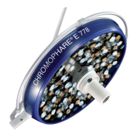
Specifies the device is designed for use in hospital treatment rooms for localized lighting.
Mandates wearing required PPE, like safety goggles, to minimize health risks during operation.
Highlights residual risks identified by analysis and advises observing safety instructions to reduce health risks.
Details DC power supply connections on the ceiling tube, including terminals and relays.
Explains 230 V AC power supply connections, including mains terminals and country-specific wiring.
Details connections for 230 V AC with emergency power relays, including input/output voltages and terminals.
Describes electrical connections on the mounting plate for various input/output voltages and CAN distribution.
Details connections for 26 V AC and 28 V DC power supplies, including input/output voltages.
Explains how to adjust brake screws for various joints to maintain light head position.
Explains how to adjust brake screw (B1) for swivel arm brakes to maintain light head position.
Details steps for adjusting spring arm brakes (B2) to control rotation and ensure stability.
Explains adjusting cardan joint brakes (B3) for classic cardanic systems to control rotation.
Explains adjusting cardan joint brakes (B3) for flat cardanic systems to control rotation.
Details adjusting light head brakes (B4) to control rotation and maintain light head position.
Describes adjusting the height stop (HB) for classic cardanic spring arms to limit vertical movement.
Details adjusting the height limit for flat cardanic spring arms using a ring nut.
Explains how to adjust spring arm tension using screw F for proper counterweight balance.
Outlines safety precautions for personnel, PPE, and general warnings for maintenance tasks.
Provides guidelines for general cleaning, disinfection, and sterilization of the operating light.
Outlines a maintenance schedule including daily, as-needed, and annual tasks and responsible personnel.
Instructs operators to perform daily function tests before using the lights.
Specifies that LED module replacement must be performed by authorized personnel due to property damage risk.
States that fuse replacement must be performed by a skilled electrician due to electrical hazards.
| Type | Surgical Light |
|---|---|
| Model | CHROMOPHARE E 668 |
| Manufacturer | Berchtold |
| Light Intensity | 160, 000 lux |
| Voltage | 100-240 V |
| Frequency | 50/60 Hz |
| Light Source | LED |
| Color Temperature | 4500 K |
| Light Field Diameter | 20 to 30 cm |
| Dimensions | Diameter: 668 mm |
| Certifications | CE |


