4
caldaie
Ball cock
Filter
Segments
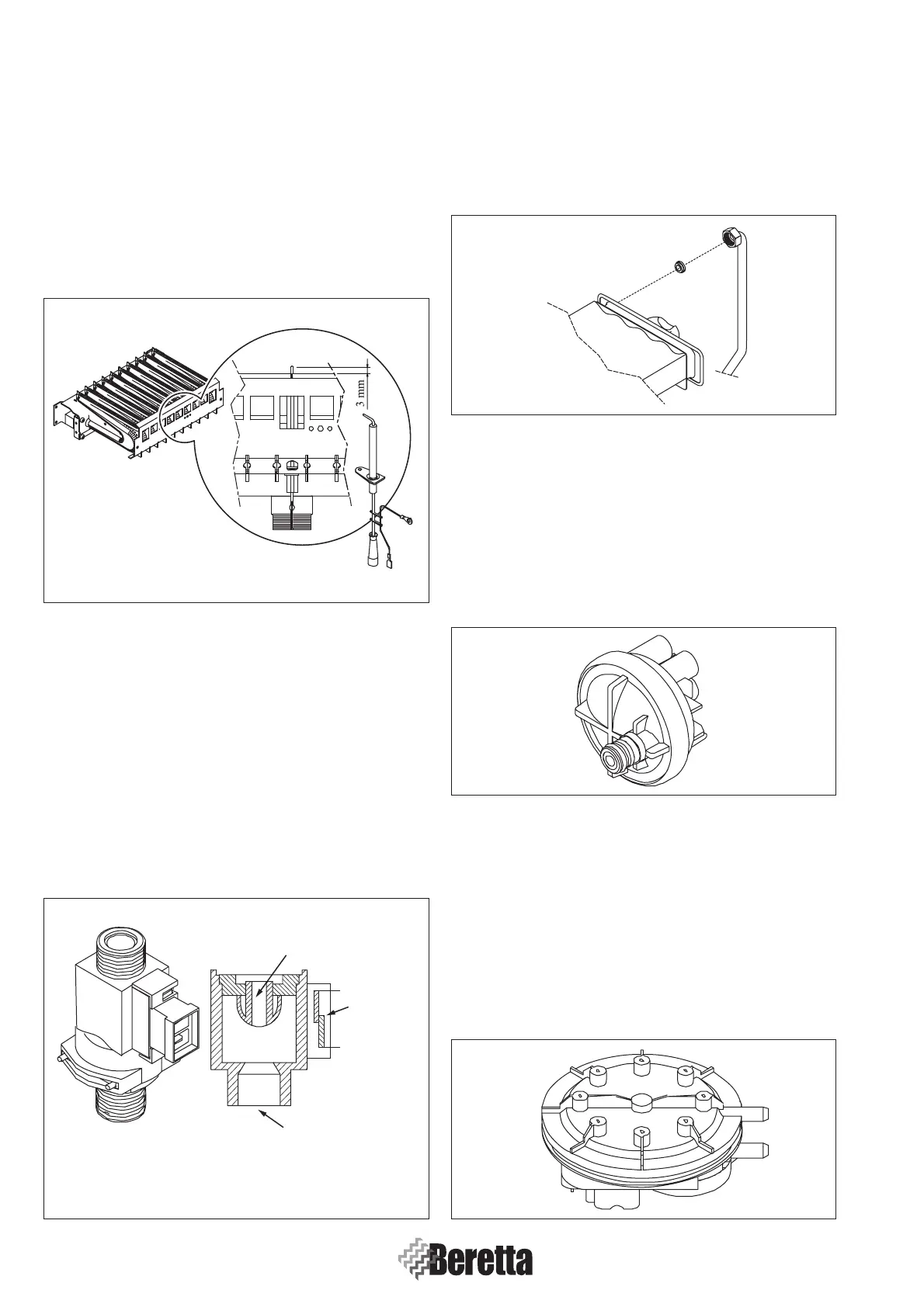
1.5.4 Igniter/control electrode
(POS. 4 APPENDIX - A page 77)
The electrode is located near the centre ramp of the burner (Sect.
1.5.1 page 3) and its job is to strike up the spark for ignition and
to control the presence of the flame.
The igniter plug consists of a metallic core and is coated on the
outside with ceramic material for electric insulation. The end
of the metal part is free from ceramic insulation and is located
at about 3 mm from the burner.
1.5.5 Flowmeter
(POS. 5 APPENDIX - A page 77)
The flowmeter is connected to the inlet on the sanitary side
of the boiler; the device is designed to control the water flow
with a ball cock consisting of a teflon spear valve, with a
magnetized sector on the upper part.
The ball cock is in stand-by position at the initial phase and the
internal contact is open. It rises as the water flows through making
the two segments come together, the flowmeter contact then closes
releasing electricity to the water in the boiler.
There is a filter at the cold water inlet to save the flowmeter
from passing impurities.
1.5.6 Flow limiter
The flow limiter is located at the inlet of sanitary water on the
bi-thermal exchanger (Sect. 1.5.10 page 5) and has the work
of reducing the sanitary water level to a maximum value of
101/min.
1.5.7 Water pressure switch
(POS. 6 APPENDIX - A page 77)
The water pressure switch is located on the right hand side of
the water heating unit; it is a device for controlling whether
there is a pressure or not in the primary system. Operating levels
are:
- ON system pressure > 0.45 bar;
- OFF system pressure < 0.45 bar.
1.5.8 Safety pressure switch (C.S.I only.)
(POS. 7 APPENDIX - A page 77)
The safety pressure switch is located on the upper part of
the air box (Sect. 1.5.11 page 5) and controls that the fan
(Sect. 1.5.20 page 7) and flues are working properly.
It consists of a double shell containing a silicone rubber
membrane. The membrane works a microswitch when the
difference in pressure indicated by the Venturi and the Pitot
tube (Sect. 1.5.21 page 7) falls to below the safety limit,
blocking the gas supply.
Fig. 1.5
Fig. 1.6
Fig. 1.7
Fig. 1.8
Fig. 1.9
 Loading...


