18
ENGLISH
See Fig. 25
b
For the minimum distances from combustible materials, see what
is reported in Fig. 27
See Fig. 27
3.4 Evacuating products of combustion
3.4.1 Models for indoor installation
)RUÀXHJDVGLVFKDUJHUHIHUWR6WDQGDUGV81,7KHÀXHJDV
exhaust/air intake kit is not supplied with the boiler as accessories for
sealed-chamber forced-draught appliances, which better adapt to the in
-
stallation context, can be used.
7R
H[WUDFW WKH ÀXH JDVHVDQG UHVWRUHWKH FRPEXVWLRQDLU LQWKH ERLOHU
use original piping or others with the same characteristics which are EC
FHUWL¿HGDQGHQVXUHWKDWWKH\DUHFRUUHFWO\FRQQHFWHGDVLQGLFDWHGLQWKH
LQVWUXFWLRQVSURYLGHGZLWKWKHÀXHJDVHVDFFHVVRULHV
$VLQJOHÀXHFDQEHFRQQHFWHGWRVHYHUDODSSOLDQFHVSURYLGHGWKDWHYHU\
appliance is sealed chamber type.
7KHERLOHULVDW\SH&DSSOLDQFHZLWKDVHDOHGFKDPEHUDQGPXVWWKHUH
-
IRUH
KDYHDVHFXUHFRQQHFWLRQWRWKHÀXHJDVHVH[KDXVWSLSHDQGFRP-
EXVWLRQ
DLULQWDNH SLSH ZKLFK ERWK ÀRZ RXWVLGH DQG ZLWKRXWZKLFK WKH
appliance cannot operate.
“FORCED OPEN” INSTALLATION (B22-B52)
7KHÀXHJDVH[KDXVWSLSHFDQEHGLUHFWHGWRWKHPRVWVXLWDEOHGLUHFWLRQ
according to installation requirements.
For installation, follow the instructions supplied with the kit.
,QWKLVFRQ¿JXUDWLRQWKHDSSOLDQFHLVFRQQHFWHGWRWKH¡PPÀXHJDV
H[KDXVWSLSHE\PHDQVRID¡PPDGDSWRU)LJ
b
,QWKLVFRQ¿JXUDWLRQWKHFRPEXVWLRQDLULVZLWKGUDZQIURPWKHURRP
where the appliance is installed, which should be technically suita-
ble and ventilated.
b
7KH QRQ LQVXODWHG ÀXHJDV RXWOHWSLSHV DUHSRWHQWLDO VRXUFHVRI
danger.
b
The table indicates the permitted linear lengths.
Model
Maximum length
Ø 80 mm (m)
Loss of load (m)
45° bend 90° bend
11-13 15 1,2 1,7
17 6 1,2 1,7
See Fig. 28
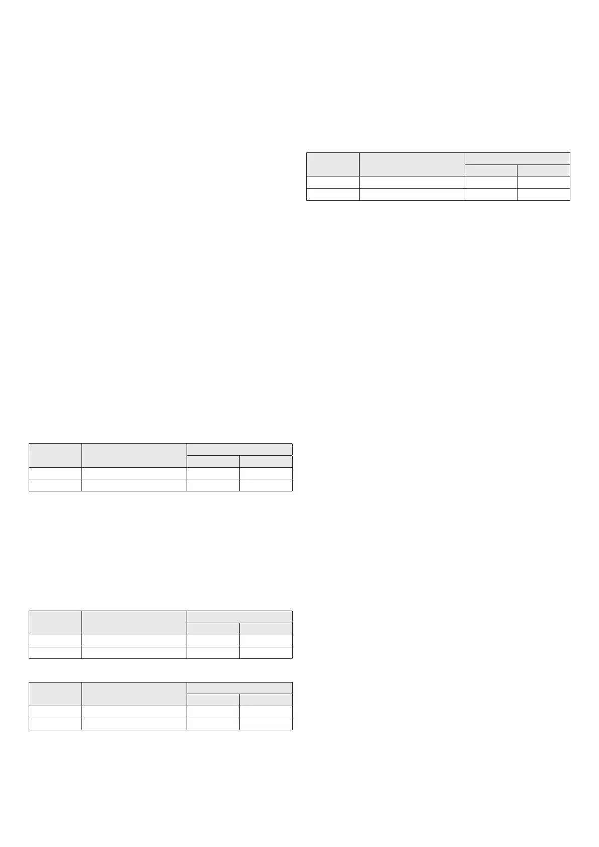
COAXIAL DISCHARGES (60-100 Ø)
The boiler has been designed to be connected to concentric discharge/
suction pipes and with the opening for air suction (
D
FORVHG)LJ
&RD[LDORXWOHWVFDQEHSRLQWHGLQWKHGLUHFWLRQPRVWVXLWHGWRWKHVSHFL¿F
installation room, in line with the lengths shown in the table.
For installation, follow the instructions supplied with the kit.
b
The table indicates the permitted linear lengths.
Horizontal
Model
Maximum length
Ø 60-100 mm (m)
Loss of load (m)
45° bend 90° bend
11-13 3,5 1 1,5
17 2,6 1 1,5
Vertical
Model
Maximum length
Ø 60-100 mm (m)
Loss of load (m)
45° bend 90° bend
11-13 4,5 1 1,5
17 3,6 1 1,5
See Fig. 29
SPLIT PIPE OUTLETS (80 Ø)
Twin outlets can be placed in the most suitable direction according to the
room requirements.
The combustion air intake pipe must be chosen from the two inlets (
E
and
F
UHPRYHWKHFORVXUHSOXJ¿[HGZLWKVFUHZVDQGXVHWKHVSHFL¿FDGDSWRU
for the chosen input.
The air inlet adaptor Ø 80 (
E
PXVWEHRULHQWHGFRUUHFWO\VRLWPXVWEH
¿[HGZLWKWKHUHODWLYHVFUHZVVRWKDWWKHSRVLWLRQLQJWDEGRHVQRWLQWHUIHUH
with the casing.
b
The table indicates the permitted linear lengths.
Model
Maximum length
Ø 80 mm (m)
Loss of load (m)
45° bend 90° bend
11-13 15+15 1,2 1,7
17 6+6 1,2 1,7
See Fig. 30 and Fig. 31
7KH¿JXUHVFig. 32 and Fig. 33 show the water heater from above with the
UHIHUHQFHSRVLWLRQVIRUWKHÀXHJDVH[KDXVWDQGFRPEXVWLRQDLULQOHWZLWK
respect to the water heater support plate.
3.4.2 Models for outdoor installation
For information on evacuating the products of combustion, please refer
to UNI 7129.
7KHDSSOLDQFHLVW\SH$DQGWKHUHIRUHKDVQRSLSHVIRUGLVFKDUJLQJÀXH
gases or a suction line for combustion air.
The combustion gases are expelled directly into the air by the integrated
outlet.
See Fig. 34
a
Avoid inhaling combustion gases.
a
Avoid direct contact with the combustion gases since they can
reach extremely high temperatures that can cause burns.
a
Avoid direct contact with the discharge since it can reach extremely
high temperatures that can cause burns.
a
To en sure th e c ombu stion ga ses are ex pelle d corre ctly, it is fo rbid -
GHQ
WRREVWUXFWRUFRYHUHYHQMXVWSDUWLDOO\WKHGLVFKDUJHRXWOHW
a
It is forbidden to loiter near the appliance when it is operating.
3.5 Electrical connections
Connect the cable supplied to the line, respecting the phase, neutral and
earth wiring. Should the power cable need to be replaced, this must be
FDUULHGRXWE\DTXDOL¿HGWHFKQLFLDQ&RQQHFWWKHDSSOLDQFHWRD+9
9)[PP
2
PD[PPFDEOHVXFKDVWKHRQHVXSSOLHGWKH
ground wire must also be 30 mm longer that the power cables. Power
to the appliance via an omnipolar switch with a gap of at least 3 mm
between contacts. For maintenance operations, cut the voltage by using
the omnipolar switch.
b
We decline all responsibility for damage to persons, animals or
REMHFWVGHULYLQJIURPWKHIDLOXUHWRHDUWKWKHDSSOLDQFHRUZLUHDQ
electrical system that complies with the standards in force.
$TXDOL¿HGSURIHVVLRQDOVKRXOGFKHFNWKDWWKHHOHFWULFDOV\VWHPLVVXLWDEOH
for the appliance’s maximum absorbed output, as shown on the plate,
ensuring particularly that the section of the system cables is suited to the
appliance’s absorbed power.
Adaptors, multiple sockets or extensions should not be used to connect
the appliance to the main power supply.
 Loading...