24
ENGLISH
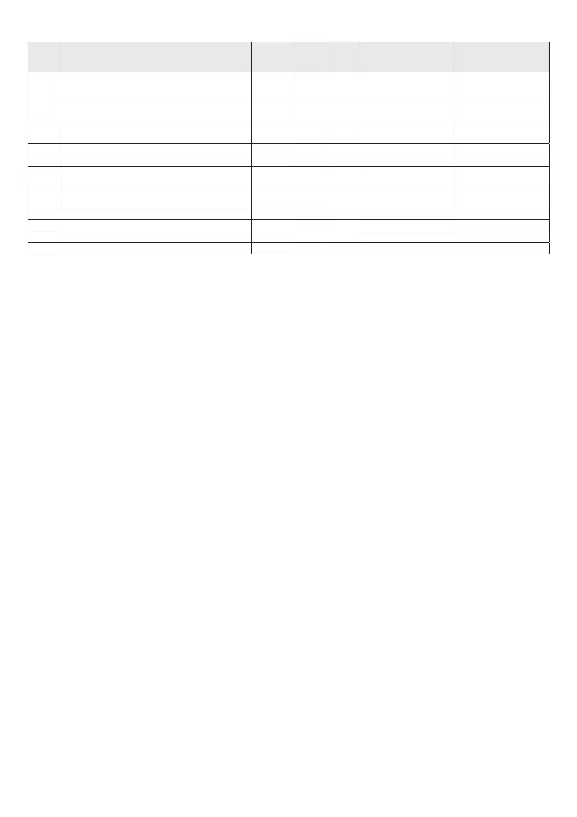
4.8.1 Table of parameters
Nr.
PAR
PARAMETER DESCRIPTION
UNIT OF
MEASURE-
MENT
MIN MAX VALUES FACTORY SETTING
2 Selecting water heater output/capacity l/min
11
13
17
11
13
17
4 Selecting methane/LPG
0(7+$1(
/3*
PHWKDQHPRGHOV
/3*PRGHOV
5 6HOHFWLQJÀRZVZLWFKÀRZLQGLFDWRU
)/2:6:,7&+
)/2:,1',&$725
0
6 Domestic hot water start wait time s 0,5 10 VWHSVRIV 0.5s
11 maximum setpoint of domestic hot water circuit °C 36 65 65
20 Induced draught protection function 01
121(
$&7,9(
1
40 Type of domestic hot water thermostat operation
$%62/87(
&255(/$7('
0
41 Displaying domestic hot water input temperature °C
42 'LVSOD\LQJGRPHVWLFKRWZDWHUÀRZUDWH NOT USED
rt Exiting the menu
rs Resetting factory settings
4.8.2 Reset to factory settings
)URPWKHSDUDPHWHUVPHQXVHOHFWLQJ³UV´DOORZV\RXWRUHVHWWKHERDUGSDUDPHWHUVWRWKHIDFWRU\VHWWLQJV5HVHWWRIDFWRU\VHWWLQJV
3UHVVLQJWKH0(18%NH\GLVSOD\VWZRXQGHUVFRUHV3UHVVWKHNH\XQWLOWKHWZRXQGHUVFRUHVVKLIWXS3UHVVWKHNH\WRUHWXUQWRIDFWRU\VHWWLQJV
,I\RXSUHVVWKH0(18%NH\LQVWHDGRIWKHNH\WKHRSHUDWLRQLVDQQXOOHGDQG\RXUHWXUQWRWKHSUHYLRXVPHQX
7RH[LWWKH7(&+1,&$/0(18SUHVVWKHRUNH\XQWLO³UW´UHWXUQLVGLVSOD\HGDWWKLVSRLQWSUHVVLQJWKH0(18%NH\UHWXUQV\RXWRWKH86(5
MENU.
3UHVVLQJWKH212))5(6(7$NH\\RXSDVVWRWKH2))VWDWH
If no action is taken, once 2 minutes have passed the appliance exits the menu and returns to the normal operation screen.
b
If you are replacing the electronic board it is necessary to set the parameters
2
DQG
4
PHWKDQHOSJGHSHQGLQJRQWKHW\SHRIZDWHU
heater used.
5 MAINTENANCE
7
To ensure c orre ct oper ation o ver tim e, the ap plia nce sho uld be ch ecked
E\DTXDOL¿HGSURIHVVLRQDODWOHDVWRQFHD\HDU
IMPORTANT
: before performing any cleaning or maintenance work, or
before opening or removing the boiler panels, turn the appliance off by
shutting off the gas tap.
Check
WKDWWKHÀXHJDVHVSDVVDJHVHFWLRQVRIWKHKHDWH[FKDQJHUDUHQRW
obstructed. Use a wet soapy cloth to clean the external panels.
Do not
use abrasive solvents, powders or sponges.
Do not
FOHDQWKHDSSOLDQFHRULWVFRPSRQHQWSDUWVZLWKKLJKO\ÀDPPDEOH
substances such as : petrol, alcohol or heavy oil.
Check
electrode position and distance.
See Fig. 39
b
Models for outdoor installation
: If you need to inspect or clean the
discharge open the cover by unscrewing the screws
A
.
See Fig. 40
6 REMOVING THE CASING
6.1 Models for indoor installation
To remo ve t he ca sing :
- disconnect the appliance from the electric power supply using the om-
nipolar switch
-
remove the two screws
A
- pull the casing
B
forwards
- lift the casing
B
upwards releasing it from the hooks at the top
See Fig. 41
Models 11-13
7R DFFHVV WKHLQVWUXPHQW SDQHOUHPRYH WKH¿[LQJ VFUHZ
C
and turn it
outwards
See Fig. 42
Models 17
To open the inst rume nt pa nel:
- remove the screws
C
- slide the instrument panel out and rotate it to the stop position
See Fig. 43
6.2 Models for outdoor installation
To remo ve t he ca sing :
- disconnect the appliance from the electric power supply using the om-
nipolar switch
-
remove the three screws
A
of the top discharge
- pull the top discharge upwards
See Fig. 44
- remove the two screws
B
- push the casing
C
forwards
- move the casing
C
upwards, freeing it from the top hooks
See Fig. 45
 Loading...