ENGLISH
ENGLISH
CHARACTERISTICS
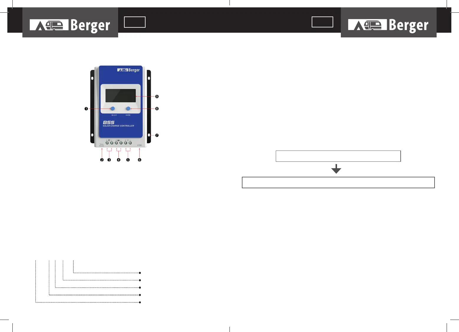
Figure 1 Product Characteristics
*If the temperature sensor is short-circuited or damaged, the controller will charge
or discharge at the default temperature setting of 25 ºC.
NAMING RULES OF CONTROLLER MODELS
Example:
1. SELECT button
2. RTS* port
3. PV Terminals
4. Battery Terminals
5. Load Terminals
6. RS485 communication port
7. Mounting Hole Φ5mm
8. ENTER button
9. LCD
Common Negative System
Max. PV open circuit voltage 100V
System Voltage 12/24VDC
Charge & discharge current 10A
Product series
MAXIMUM POWER POINT TRACKING TECHNOLOGY
Due to the nonlinear characteristics of solar array, there is a maximum energy output point
(Max Power Point) on its curve. Traditional controllers, with switch charging technology and
PWM charging technology, can’t charge the battery at the maximum power point, so can’t
harvest the maximum energy available from PV array, but the solar charge controller with
Maximum Power Point Tracking (MPPT) Technology can lock on the point to harvest the
maximum energy and deliver it to the battery.
The MPPT algorithm of our company continuously compares and adjusts the operating
points to attempt to locate the maximum power point of the array. The tracking process is
fully automatic and does not need user adjustment.
As the Figure 1-2, the curve is also the characteristic curve of the array, the MPPT techno-
logy will ‘boost’ the battery charge current through tracking the MPP. Assuming 100%
conversion effi ciency of the solar system, in that way, the following formula is established:
Normally, the VMpp is always higher than VBat, Due to the principle of conservation of
energy, the IBat is always higher than IPV. The greater the discrepancy between VMpp
&VBat, the greater the discrepancy between IPV& IBat. The greater the discrepancy bet-
ween array and battery, the bigger reduction of the conversion effi ciency of the system,
thus the controller’s conversion effi ciency is particularly important in the PV system.
Figure 1-2 is the maximum power point curve, the shaded area is charging range of traditio-
nal solar charge controller (PWM Charging Mode), it can obviously diagnose that the MPPT
mode can improve the usage of the solar energy resource. According to our test, the MPPT
controller can raise 20%-30% effi ciency compared to the PWM controller. (Value may be
fl uctuant due to the infl uence of the ambient circumstance and energy loss.)
Input power (P
PV
) = Output power (P
Bat
)
Input voltage (V
Mpp
) *input current (I
PV
) = Battery voltage (V
Bat
) *battery current (I
Bat
)
BSS 0 2 1 1
36
37
 Loading...