ENGLISH
ENGLISH
NOTE: All PV modules in a given array are assumed to be identical.
*Isc=short circuit current(amps) Voc=open circuit voltage.
*These are the maximum wire sizes that will fit the controller terminals.
CAUTION: When the PV modules connect in series, the open circuit voltage of the PV array
must not exceed 92V at 25° C environment temperature.
Battery and Load Wire Size
The battery and load wire size must conform to the rated current, the reference size as
below:
CAUTION: For the battery, the recommended wire will be selected according to the condi
-
tions that its terminals are not connected to any additional inverter.
MOUNTING
WARNING: Risk of explosion!
Never install the controller in a sealed enclose with flooded batteries! Do not install in a
confined area where battery gas can accumulate.
WARNING: Risk of electric shock!
When wiring the solar modules, the PV array can produce a high open circuit voltage, so
turn off the breaker before wiring and be careful when wiring.
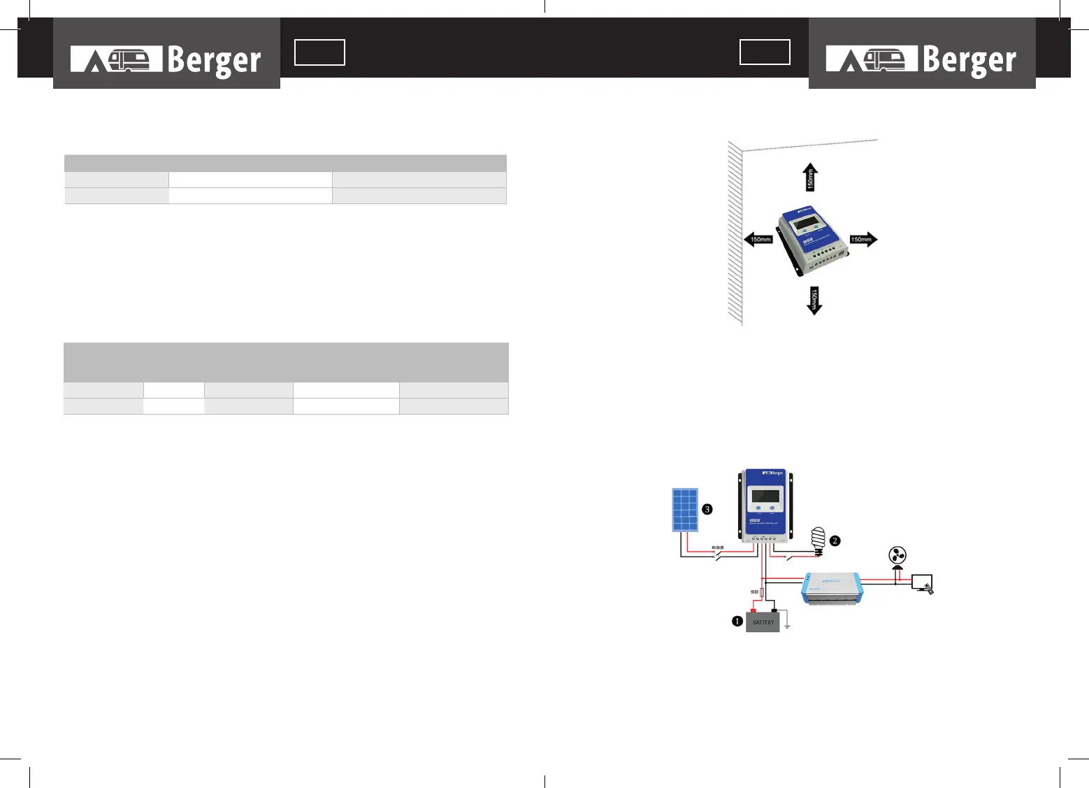
CAUTION: The controller requires at least 150mm of clearance above and below for proper
air flow. Ventilation is highly recommended if mounted in an enclosure.
INSTALLATION PROCEDURE:
Figure 2-1 Mounting
Step 1: Determination of Installation Location and Heat-dissipation Space
Determination of installation location: The controller shall be installed in a place with suf
-
ficient air flow through the radiators of the controller and a minimum clearance of 150 mm
from the upper and lower edges of the controller to ensure natural thermal convection.
Please see Figure 2-1: Mounting
CAUTION: If the controller is to be installed in an enclosed box, it is important to ensure
reliable heat dissipation through the box.
Figure 2-2 Schematic of wiring diagram
Step 2: Connect the system in the order of (1) battery -> (2) load -> (3) PV array in ac
-
cordance with Figure 2-2,”Schematic Wiring Diagram” and disconnect the system in the
reverse order (3) (2) (1)
Model Max. PV input current Max. PV wire size*
BSS0211 10A 4 mm
2
/ 12AWG
BSS1184 20A 6 mm
2
/ 10AWG
Model Rated
charge
current
Rated dischar-
ge current
Battery wire size Load wire
BSS0211 10A 10A 4 mm
2
/ 12AWG 4 mm
2
/ 12AWG
BSS1184 20A 20A 6 mm
2
/ 10AWG 6 mm
2
/ 10AWG
44
45