Be242 Be242RB Be242-22 OEM's Manual V4.X.XX - March - 2023 page 20
Follow the instructions:
A) - Remove the battery power supply; disconnect all connectors and disconnect the Mains/Generator plugs.
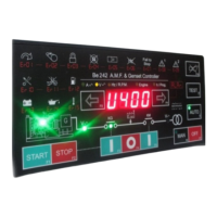
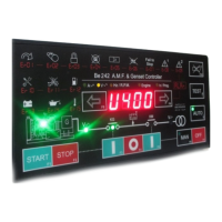
B) - Push and hold the [ACK-F10] push button amd apply the Vdc power supply; all LEDs/Display turn on.
C) - Release the button when you have verified all indicators; the LEDs will turn off and the message [- - - -] will
be displayed.
NOTE - At this stage of the TEST, if the display indicates one of the codes contained in Table 13.1 or
13.2, the Be242 is damaged and should be returned to Bernini Design.
To exit the Troubleshooting, remove the Vdc supply at anytime
13.1 Testing the Push buttons
A) - Push the push buttons on the front panel one by one. The display will show a message according to Table
13.1. As soon as you release all buttons, the message [- - - -] will be displayed.
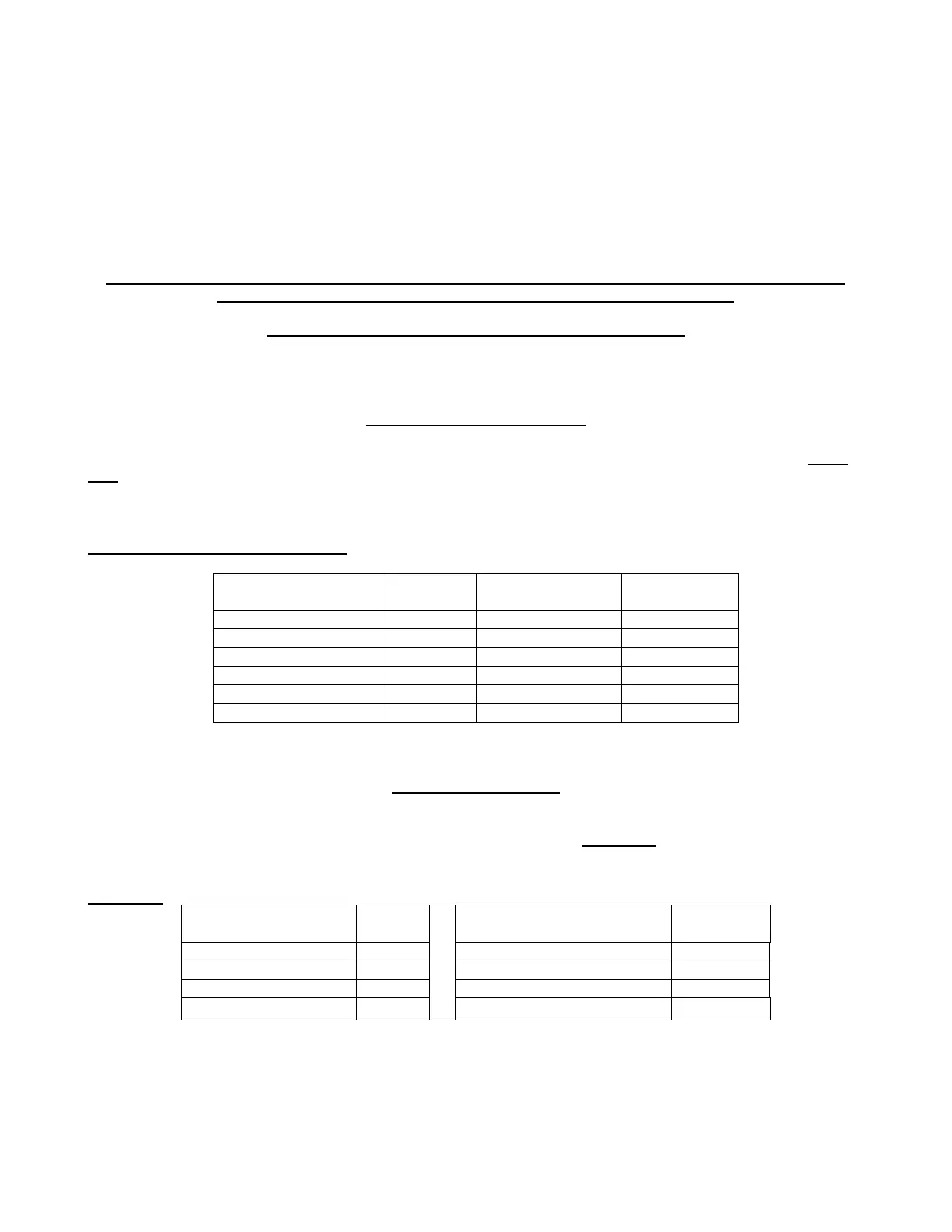
Table 13.1: Push buttons true table
13.2 Testing the Inputs
Push and hold the [ACK-F10] button until the message [-in-] appears. Connect, one by one, inputs #9 to #14 to
the battery minus. For each input, a code will be displayed according to Table 13.2. If more than one input is
connected together (or some of them are in short circuit), the display indicates the messages in sequence.
Table 13.2
Terminal number
(function)
Terminal number
(function)