Be242 Be242RB Be242-22 OEM's Manual V4.X.XX - March - 2023 page 4
Section 1.0 Introduction
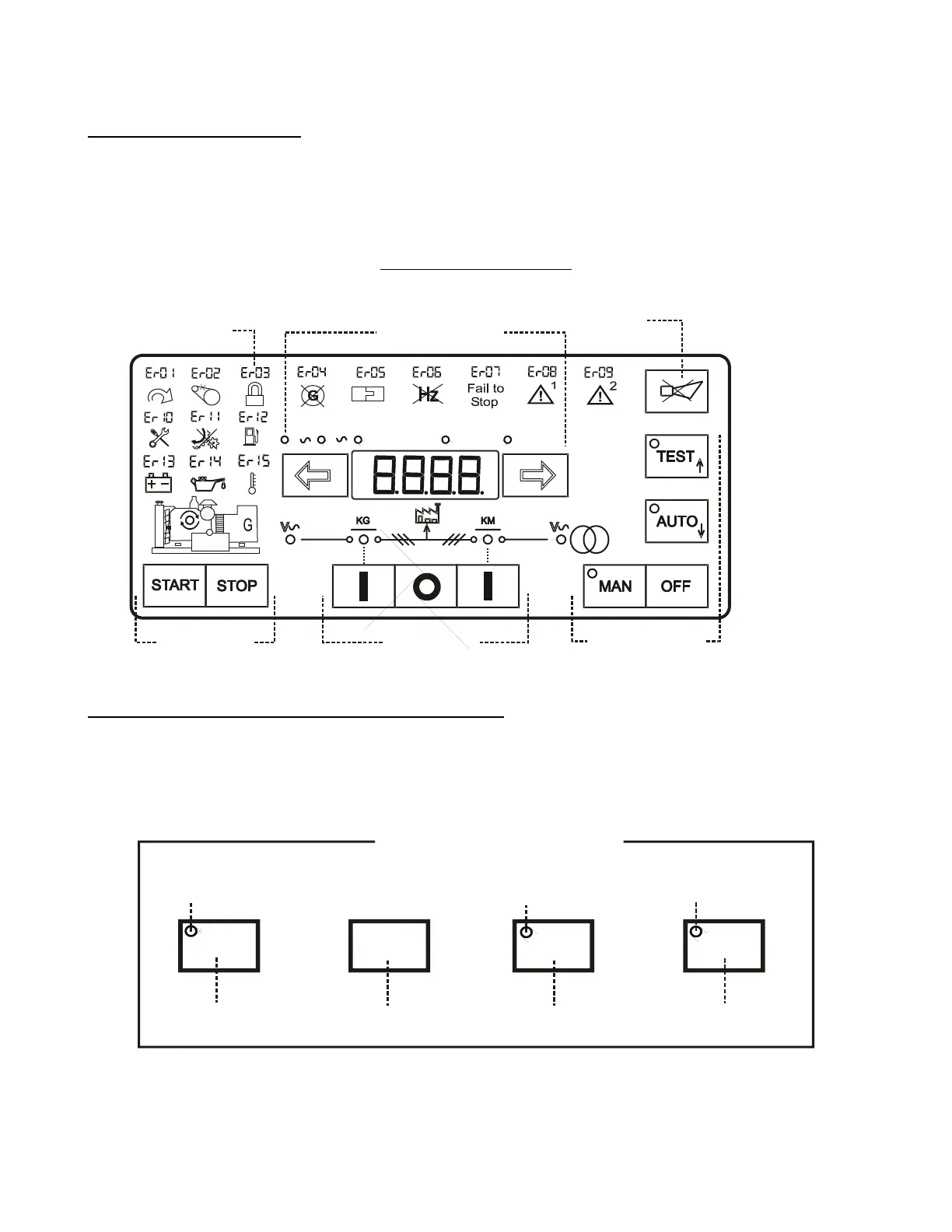
The Be242 is a 3-Phase AMF/Genset controller. The Be242 provides visual indication by means of LEDs and
Displays for Engine & Electrical parameters, Alarms and Status of the contactors.Figure 1 presents the panel
layout. The Be242 is connected to the Be242RB (Relay Board) via a 25 poles shielded cable supplied in the
BE242 KIT box. This controller is suitable for replacing the Be22 AMF controller.
Figure 1: Front Panel layout
Section 2.0: Selection of the Mode of operation
When you apply the DC supply, the display indicates for a second, the version of the software (example 1.0.01)
and the detected kind of battery (12V or 24V) Should the battery supply be lower than 7,5V, the BE242 will
trigger the [ER.13] alarm code; the software will not run. The modes of operation are selected by push buttons
and indicated by means of green LED indicators as shown below:
TEST AUTO
OFF
MAN OFF TEST
AUTO
Pushbutton
Pushbutton
Pushbutton
Pushbutton
MANUAL Mode
green LED
Operating Modes Pusbuttons
TEST Mode
green LED
AUTO Mode
green LED
Operating Modes
Note: default programming for emergency input is ‘normally closed ‘. To inhibit the alarm [Er.08]
you are required to connect terminal JH4 to JH1 (Emergency input) on the back of the controller. You
can reverse the contact by changing the type of the contact (see P35 on table 7.04).