Be242 Be242RB Be242-22 OEM's Manual V4.X.XX - March - 2023 page 19
Section 11.0 Engine Running Detect (Charger Alternator)
The Be242 inhibits the starter motor when the engine starts running. When the engine is not running, the voltage
in terminal D+/WL of the charger alternator (input #15) is 0 V. As soon as the Be242 starts the engine, a voltage
appears in the D+/WL terminal (0.8 to 2.5 V). When the engine starts running, the voltage of the D+/WL terminal
increases by up to 3 V - 6 V. When the engine runs, the voltage reaches 14 V (28 V) needed to charge the
battery. The safest point to disconnect the starter motor is between 6 V to 10 V. The default parameter of [P.26]
is 8.0 V. This value is recommended for engines using 12 V batteries. For 24 V batteries, we recommend that
you set the threshold to 16 V.
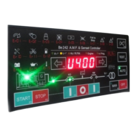
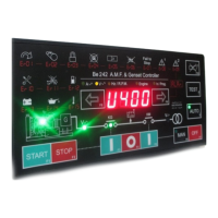
For safe calibration, ensure the green ‘ENGINE RUNNING’ LED on the front panel is off during all of the starting
attempts. The Charger Alternator voltage can be displayed in the 'Engine menu' as indicated in section 3.0. For
Flywheel chargers, the reading is not accurate. The [P.26] setting, in this case, expresses only a proportional
factor.
The Be242 also uses the output of the Generator in order to disconnect the crank motor. Parameters [P.27] and
[P.28] set the crank termination. These parameters do not affect the status of the green ‘ENGINE RUNNING’
LED.
NOTE: THE ‘ENGINE RUNNING’ LED MUST BE LIT WHEN THE ENGINE RUNS. USING THE ENGINE
WITHOUT THIS SIGNAL MAY BE DANGEROUS.
Normally, using a diesel engine, we recommend enabling the BELT BREAK protection. This is accomplished by
programming a voltage setting in the [P.26] sub-menu. To test the efficiency of this protection, disconnect
terminal D+ from the charger alternator and connect to ground the #15 terminal. This protection is delayed by 15
seconds.
Section 12.0 - Memory Reset
12.3 - To clear the Memory
- Remove the supply. Push and hold the [I-F3] & [I-F5] push buttons simultaneously and apply the Vdc supply.
- As soon as the message AUTO-TEST appears, release the push buttons; the display will indicate [ F1].
- Push [F1] and then push, one by one, all push buttons indicated by the message on display.
- After pushing the last push button ([AUTO]), the message [-EPP] will appear; wait a few seconds.
- The memory, now, is erased. The Be242 will use the factory-programmed parameters (defaults).
- Remove the supply and re-program the controller according to your need. We always recommend that you
program a password in order to limit access (see section 6.40).
Section 13.0 Troubleshooting Guide
The Basic Troubleshooting Guide is intended to provide you with a guide to problems that you may experience
with the Be242. We recommend that you disconnect all removable terminal blocks from the BE242RB interface
board. This procedure should only be carried out by qualified personnel.
To exit the Troubleshooting, remove the Vdc supply at anytime
! W A R N I N G ! High voltage is inside the Be242. To avoid electric-shock hazards, operating personnel
must not remove the protective cover. Do not disconnect the Earth connection. Any interruption of the grounding
connection can create an electric shock hazard. Before making external connections, always ground the B242
first by connecting the control panel to the ground.