22
WATER OF THE RINSING TANK
• Remove the Camlock cap from the auxiliary outlet
on the front of the towed tank and connect the
accessory to be used.
• Power take-off stopped, place (fi gure 25):
- The valve (A) on function
.
- The valve (B) on function
.
- The valve (C) on function
.
- The valve (D) on function
.
• Engage the tractor’s power take-off and raise its
rotation speed to 300 rpm.
• Place the valve (C) on function (fi gure 26).
• When the operation is over, lower the engine speed
of the tractor until it is at idle, then release the power
take-off.
• Place (fi gure 24):
- The valve (A) on function
.
- The valve (B) on function
.
- The valve (C) on function
.
- The valve (D) on function .
• Put back the Camlock cap on the auxiliary outlet.
WATER OF THE MAIN TANK
• Remove the Camlock cap from the auxiliary outlet
on the front of the towed tank and connect the
accessory to be used.
• Power take-off stopped, place (fi gure 21):
- The valve (A) on function
.
- The valve (B) on function .
- The valve (C) on function
.
- The valve (D) on function
.
• Engage the tractor’s power take-off and raise its
rotation speed to 300 rpm.
• Place the valve (C) on function (fi gure 22).
• If required, stop the mixing at the bottom of the
tank by switching valve (B) to function
(fi gure 23).
• When the operation is over, lower the engine speed
of the tractor until it is at idle, then release the power
take-off.
• Place (fi gure 24):
- The valve (A) on function
.
- The valve (B) on function
.
- The valve (C) on function
.
- The valve (D) on function .
• Put back the Camlock cap on the auxiliary outlet.
3.4. USING THE AUXILIARY OUTLET (OPTIONAL)
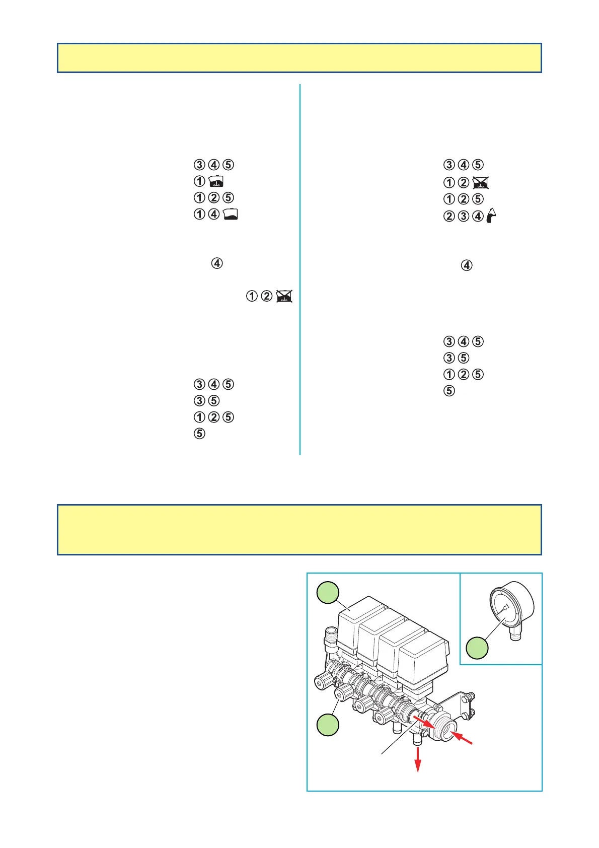
3.5. ADJUSTMENT OF THE COMPENSATED
RETURN
(OPTIONAL)
• The distribution unit is made up of electric fl ap
valves (V.E.C.) (1), for each spraying section. These
electric fl ap valves supply each section when they
are in "open" position and the return to the tank
when they are in "closed" position.
• Return to the tank is calibrated by means of a
micrometric screw (2).
• Adjust the screw (2) to obtain the same pressure
as at the pressure gauge (3), in both "closed" or
"opened" positions (perform this operation for each
electric fl ap valve by using clean water).
• Use the switches (6) and (7) (see page 12 or 13)
to open or close spraying.
3
1
2
Supply
Return to tank
Boom