Technical data
3-5
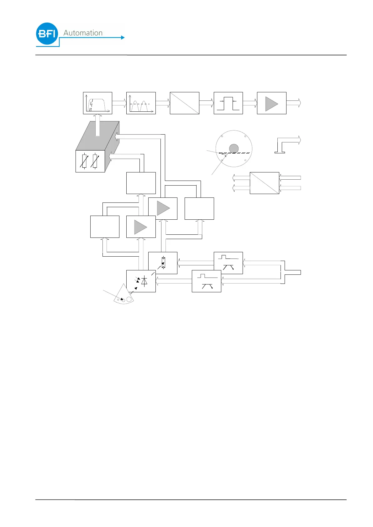
3.6 Device design - block diagram of the flame scanner
AGC
AGC
AFC
DC
DC
U
F
A
1
3
4
5
2
B
B
PbS
Si
C
D
D
E
F G H J K
O
M
L
N
R
Q
P
1 – 5 pin number in the Harting plug J pulse shaper
system shutter puls K output stage
B electronic shutter L signal output
C optical aperture M Signal GND
D pre-amplifier N power supply
E mixing stage O DC/DC Converter
F band pass P lens plate
G full-wave rectifier Q potentiometer for UV-NIR
H U/F converter R potentiometer for NIR-IR
Si semi-conductor sensor Si (UV-NIR) AGC automatic gain control
PbS semi-conductor sensor PbS (NIR-IR) AFC automatic frequency control
 Loading...