Transport, installation and connection
4-9
Prior to the connection of the flame scanner, observe the
separate operating instructions of the flame amplifier
(System 3000 / 4000) !
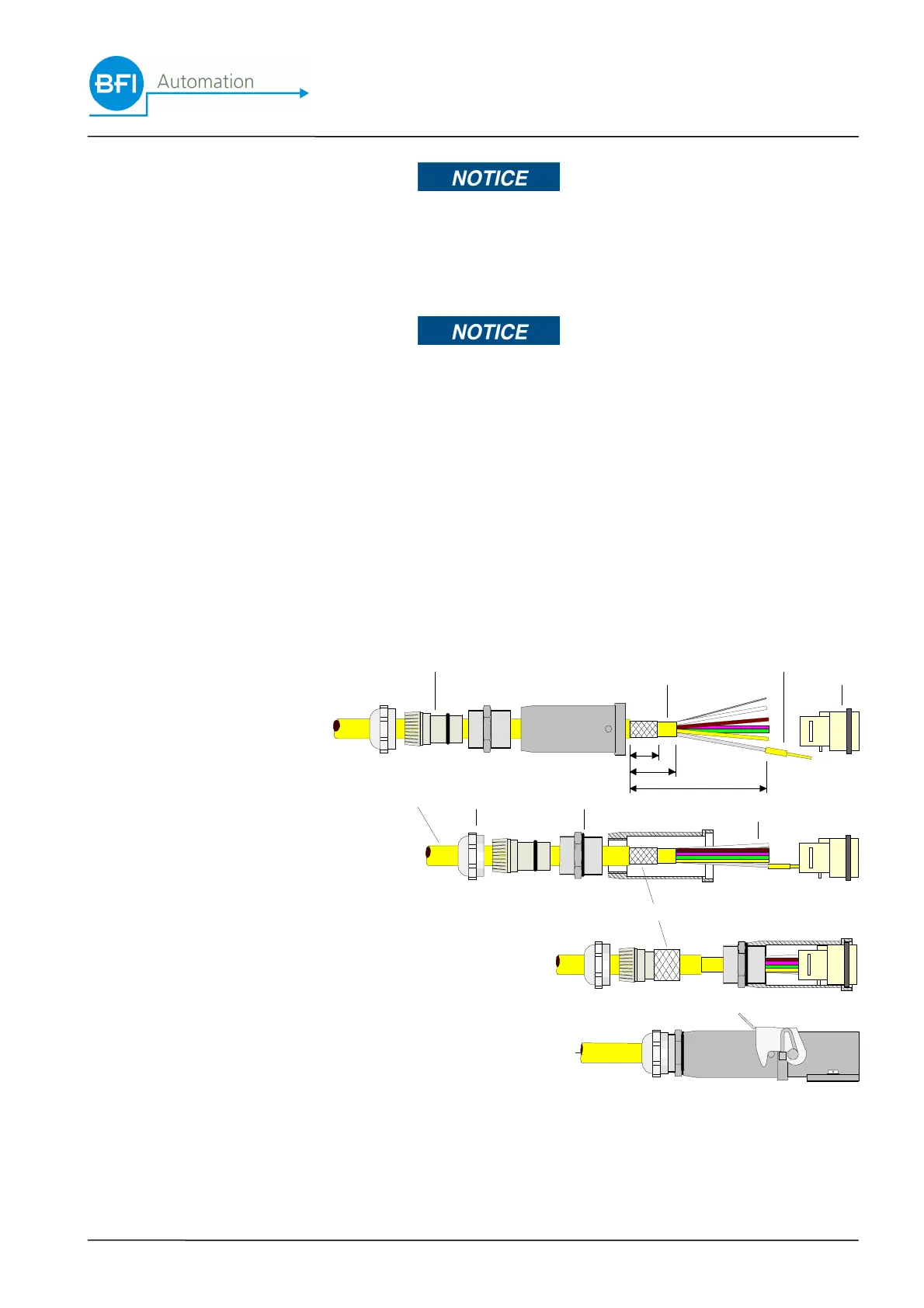
4.7.2 Laying the special cable KW5
No contact chamber may remain bare !
All contact chambers in the contact insert have to be fitted
with crimp contacts !
For this purpose use a suitable crimp tool (BFI part No.
8980-4801-00) !
On the flame scanner side the external shielding is con-
nected to the housing mass by means of a clamp connec-
tion located between the plastic insert the threaded part in
the cable gland (not available in KW3 cable). The internal
shielding is cut on the flame scanner side and is con-
nected to the flame amplifier side along with the signal
GND (see terminal diagram).
A: external PUR shielding
B: union joint
C: plastic insert
D: threaded part
E: external shield
F: internal PUR shielding
G: individual wires
H: crimp contact
J: female contact
J
H
F
A
C
D
B
G
15
20
55
E

 Loading...