Transport, installation and connection
4-3
2
3
4
5
1
4.6 Installation
All installation and connection work may be carried out by
qualified and approved specialist staff only ! The legal
regulations as well as adjustment instructions of the plant
operator have to be observed !
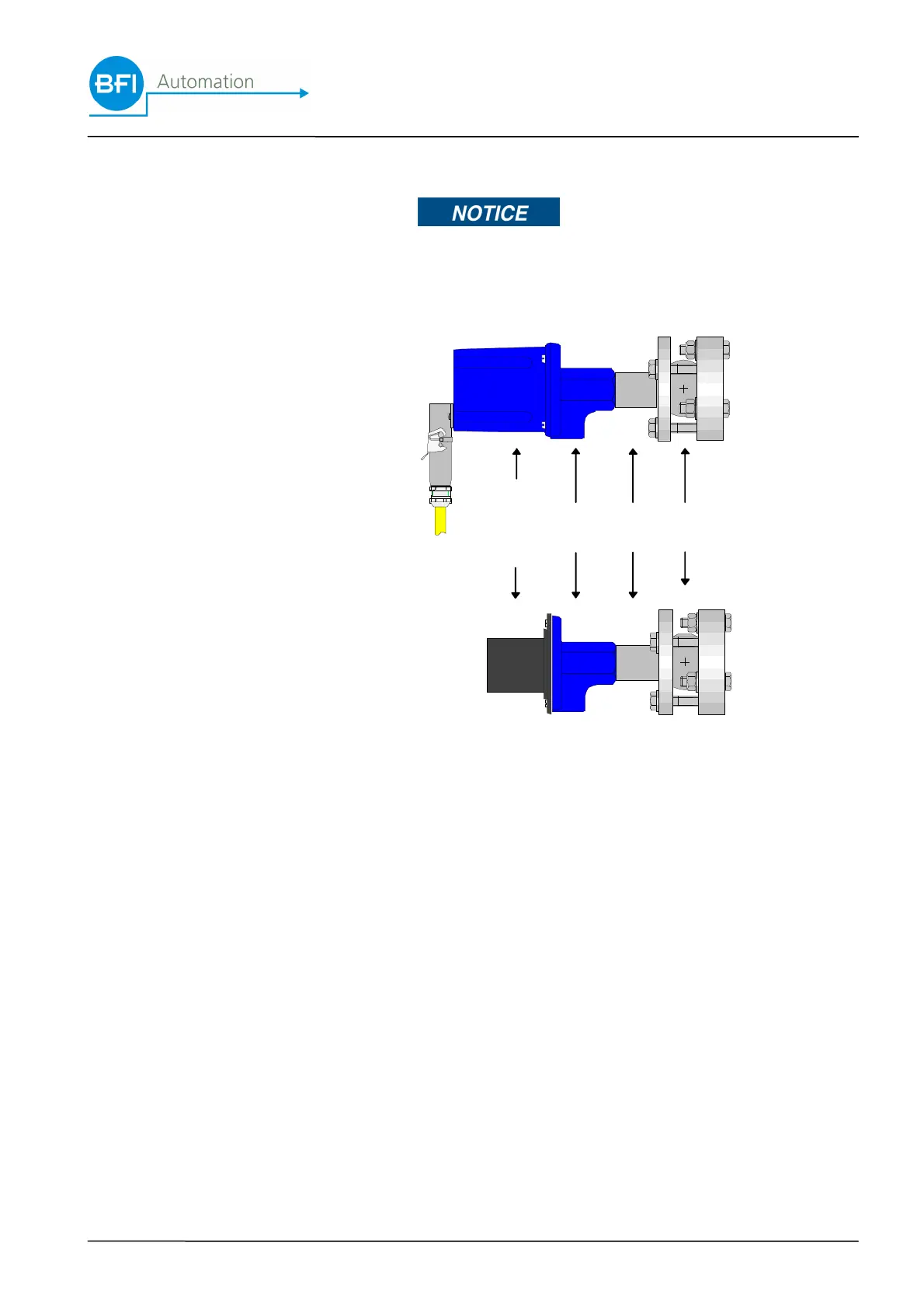
1 Flame scanner
2 Optical alignment
device
3 Purge air flange
4 Heating insulator
5 Ball-flange
The flame scanner has been provided with oblong holes
for easy installation on the purge air flange. Counter all
four M5 screws with nuts and fit U-disks and lock wash-
ers.
The sighting tube connection has been provided with a
G1" internal thread.
In order to ensure perfect flame amplifiering, the correct
and low-vibration position of the sighting tube relative to
the flame is essential. The flame scanner has to be
aligned in such a way that a perfect visual image is set.
For this purpose use the optical adjusting device (avail-
able as an accessory) as shown in the following illustra-
tion.
 Loading...