Transport, installation and connection
4-5
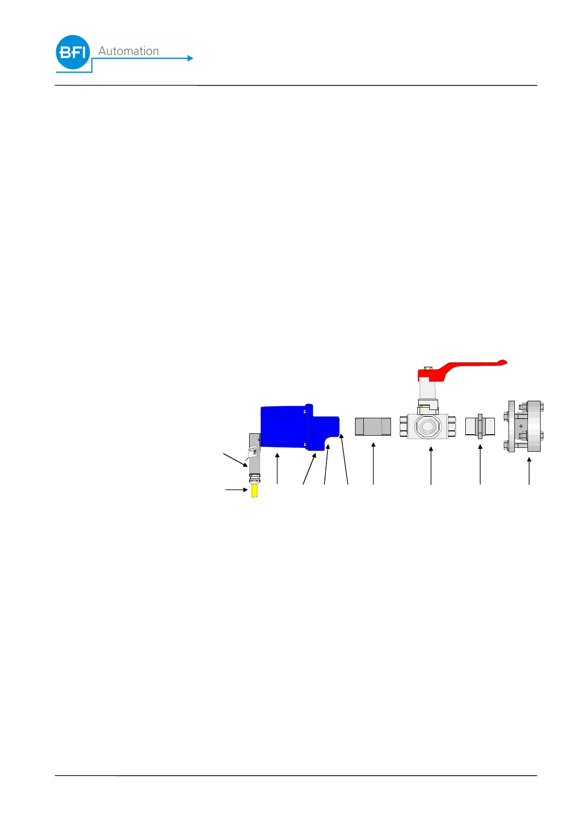
By using a ball-flange (optional, part No. 6590-9020-01),
the adjustment can be carried out easily ensuring that the
ideal sighting point is set mechanically. The flame scan-
ner is supplied complete with a rapid-installation flange.
This flange ensures the unproblematic disassembly of the
flame scanner. It has a purge air connection, the con-
struction of which prevents the soiling of the lens system
without the dust-laden purge air damaging the lens. If
temperatures of over 50 degrees Celsius occur at the
flame scanner despite the inflow of cooling air caused by
the heat dissipation of the sighting tube, heating insulator
(optional, part No. B 512.1) has to be used. In case of
pressurised combustion, an additional 3-way-ball-valve
(optional, part No. B 520) has to be fitted for protection.
The exit of hot gas after removal of the scanner is pre-
vented, ensuring further cooling and purging of the ar-
rangement.
The entire mechanical peripheral system can be supplied
by BFI Automation.
1
2
3 98
7
4 5 6 10
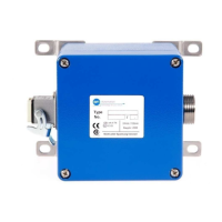
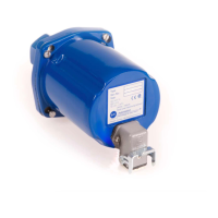
1 Harting plug
2 Special cable KW5
3 Flame scanner
4 Purge air connection
5 Purge air flange
6 Sighting tube con-
nection
7 Heating insulator
8 3-way-ball-valve
9 Double nipple
10 Ball-flange
 Loading...