- 26 -
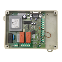
Control unit
EN
The following table gives the 4rd level functions and the single parameters.
= DEFAULT value set in factory.
= parameter value set during installation: must be indicated
if DEFAULT value is modi ed.
8.5
4TH
LEVEL PROGRAMMING
Descrizione parametri livello 4
· :
Setting communication protocol.
Set value always same to Master and Slave.
·
:
Impostazione U-LINK mode.
·
:
Setting U-LINK adress.
Par Function Settable data
Communication protocol
: disabled
: U-LINK
: Modbus/RTU
U-LINK mode
: Slave
: Master
: Slave for opposing barriers
: Master for opposing barriers
U-LINK adress
Modbus/RTU ID
: For Slave
: For Master
MODBUS RTU speed
: 19 200 band
: 38 400 band
· :
Setting Modbus/RTU ID.
·
:
Setting MODBUS RTU speed
Set value always same to Master and Slave.
Description of level 3 parameters
·
, , , :Output polarity
Output polarity: The outputs can be con gured as N.O. or N.C. but, in the event of a blackout the contacts open anyway.
·
:Velocity selection input
By enabling this parameter bar speed can be adjusted via the PDM input.
If the PDM is activated and parameter enabled the barrier moves at a speed equal to 60% of maximum speed, both when ope-
ning and closing.
·
:Advance electric lock disengagement
This parameter adjusts the delay between electo-lock deactivation and engine start , to allow the resetting of the residual magneti-
sm of the electro lock.
·
:Advanced setup
This parameter enables the use of special con gurations to cater for speci c necessities.
N/A.
Controlled entry and automatic exit (see paragraph 11).
· : Swinging boom sensor input N.C.
swingin boom sensor not mounted or disabled
automation stops immediately in case of swinging boom opened
Closing speed (%)
- (MAXIMA ULTRA 68, ATM 90°, ATM 180°)
- (MAXIMA ULTRA 35, Carbon)
Speed selection input
: Disabled
: Enabled
Swinging boom sensor input
: swinging boom not mounted or disabled
: swinging boom sensor mounted and activated N.C.
Exiting the menu/saving
Exit programming and view machine status (see notes St automation
status display after the 1st level table)
ENGLISH