- 18 -
Control unit
EN
The control unit has been developed to control automatic single-phase barriers with inverter-driven three-phase motor.
1. INTRODUCTION
- Microprocessor logic
- LEDs displaying inputs/outputs status
- Integrated radio receiver 433.92MHz, 2 channels, 2 048 codes
- TCP/IP module and RS485 module (Option)
2. MAIN CHARACTERISTICS
F
J10
J9
J6J5
J12
J8
J2
J3
J4
J1
F2
F1
F3
F4
J7
J11
K2 K3 K4 K5
PR2
K1
DL
PR1
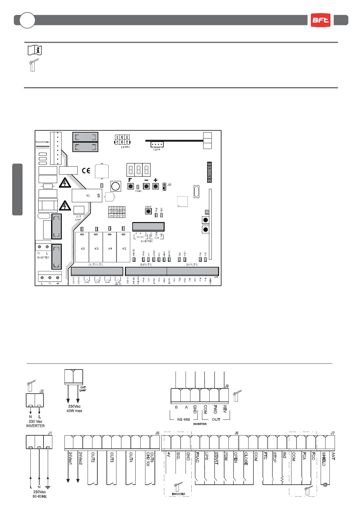
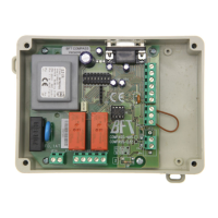
= Electrical connections con gured at the factory.
J1: Control unit power supply
J2: Inverter power supply
J3: Transformer connector
J4: Flashing light output
J5: Outputs/accessories power supply
J6: Encoder/inputs
J7: Inputs/antenna
J8: Boom lights connector
J9: Inverter signals
J10: Expansion connector
J12:
Radio programmer connector
DL: 3-digit LED display
START: “START” control button
F1: Transformer primary fuse: 500 mAT (230Vac) - 1 AT (115Vac) 5x20mm
F2: Line fuse (control board and inverter): 4 AT (230Vac) - 8 AT (115Vac) 5x20 mm
F3, F4: Transformer secondaries fuses: 2 AT 5x20mm
F, - , + : Programming push buttons
PR1, PR2:
Radio receiver
programming push buttons
- 3-digit display for programming and system status
- Up to 4 con gurable outputs
- Radio programmer connector
- Built-in heater for cold climates (Termon)
ANT
SHIELD
START
PDM
OPEN
CLOSE
COM
FTC
STOP
8k2
COM
FCA
FCC
OUT2
OUT3
OUT4
OUT5
+V
SIG.
GND
ENCODER
INVERTER
CH2 RX
24Vac1
24Vac2
FRAC
UPS
J7
J6
FWD
REV
B A
GND
COM
J9
J5J1
RS 485 OUT
L N
J2
230Vac
50-60Hz
OUT
LAMP
230Vac
40W max
230 Vac
INVERTER
N L
ENGLISH