12’–24’ BASIC 6
®
WWW.BIGASSFANS.COM ©2012 DELTA T CORP. ALL RIGHTS RESERVED
6
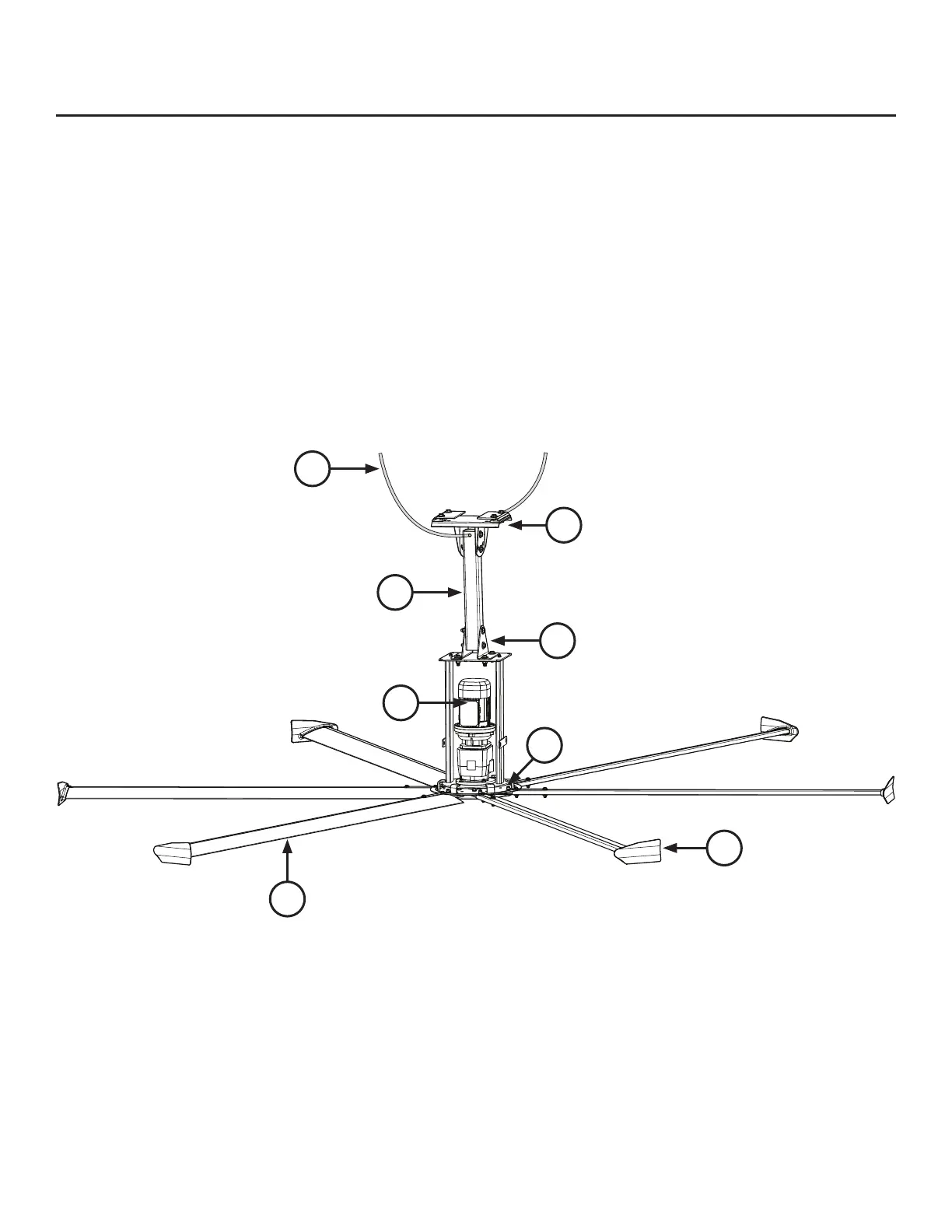
Fan diagram
A. Safety Cable. A redundant safety feature that secures the fan to the mounting structure.
B. Upper Yoke. Secures the fan to the mounting structure and allows the fan to adjust its center of gravity. Note: The upper yoke may
differ from the illustration below.
C. Extension Tube. Extends the fan from the ceiling.
D. Lower Yoke. Connects main fan unit to the extension tube.
E. Motor. See page 2 for technical specications.
F. Hub. Secures the airfoils to the gearbox.
G. Airfoil. Provides air movement. The unique, patented design provides efciency and effective air movement.
H. Winglet. Improves the efciency of the fan.
Pre-Installation (cont.)
F
H
E
C
D
B
A
G