12’–24’ BASIC 6
®
7
WWW.BIGASSFANS.COM ©2012 DELTA T CORP. ALL RIGHTS RESERVED
12’–24’ BASIC 6
®
Preparing the work site
Before beginning installation, review the mechanical and electrical installation guidelines below.
Mechanical installation
• A 24-ft (7.3-m) Basic 6
®
fan (largest model) with a 1-ft extension tube weighs, at maximum, 241 lbs (109 kg). A suitable means for
lifting the weight of the fan, such as a scissor lift, and at least two installation personnel will be required.
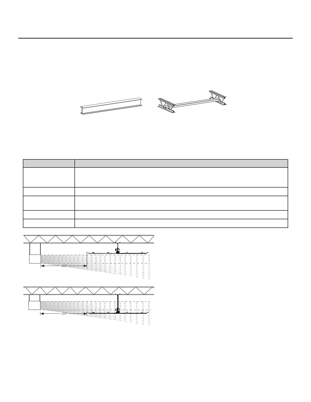
• Big Ass Fans can only be hung from an I-beam or angle irons. For specic requirements, see the Mechanical Installation section
in this guide. Do not mount the fan to single purlins, trusses, or bar joists. Consult a structural engineer for installation methods not
covered in this manual.
• The mounting structure must be able to withstand the torque forces generated by the fan. A 24-ft fan generates nearly 300 ft·lb
(406.7 N·m) of torque during operation.
• Fans mounted on fabricated I-beams, which are common in steel buildings, could cause the beam to ex and the fan to move
signicantly during operation. If this exing causes a clearance problem we suggest installing I-Beam Stabilizer kit.
• If the fan’s extension tube is 4 ft (1.2 m) or longer or if the mounting structure requires it, the fan’s lateral movement must be secured
using guy wires. If the fan is close to any building xtures it is recommended to secure the fan with guy wires as a safety measure.
• Adhere to the safety requirements in the table below when selecting the fan location.
Safety requirement Minimum distances
Clearance
≥2 ft from all fan parts. The fan installation area must be free of obstructions such as lights, cables,
sprinklers, or other building structure. See the table on page 2 for recommended minimum ceiling
clearances.
Blade height ≥10 ft above the floor
HVAC equipment
≥1x fan diameter if at same level or above diffuser. ≥2x fan diameter if below diffuser. Refer to the
illustration below.
Fan spacing 2.5x fan diameter, center-to-center
Radiant/IR heaters See the manufacturer’s requirements for the minimum clearance to combustibles.
Electrical installation
• To reduce the risk of electric shock, wiring should be performed by a qualied electrician! Incorrect assembly can cause electric
shock or damage the motor and the controller!
• The installation of a Big Ass Fan must be in accordance with the National Electrical Code, ANSI/NFPA 70-2011, and all local codes.
• Refer to the Electrical Installation section in this manual for acceptable cable types, conduit, and other electrical requirements.
• Controller output/motor input leads cannot share a conduit with any other controller’s AC supply feed.
• If you are installing an onboard variable frequency drive (VFD), route the power wiring to the location where the fan will be mounted.
Pre-Installation (cont.)
I-Beam Angle Iron
HVAC
Diffuser
≥1x fan’s diameter (24 ft)
24-ft diameter
24-ft diameter
HVAC
Diffuser
≥2x fan’s diameter (48 ft)
The fan is located at or above
the HVAC discharge or intake.
The fan is located below the
HVAC discharge or intake.