12
3. Fasten one of the chains (E) to the tie rod of the
bracket farther from the motor by opening, positioning,
andresealingitsnalchainlink.
If necessary, repeat the process to connect the two
chains to one another or even to add additional lengths
of chain.
ONLY use ANSI #41 chain with this device and do
not use any chain longer than 40 feet (12 m).
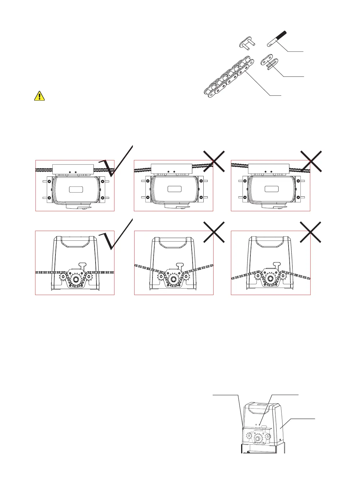
4. Adjust the length of your chain so that it will be roughly taut—neither loose nor tight—once
threadedthroughthemotorandattachedtotheotherbracket.Conrmthatthechainwillrun
straight from one bracket to the other without requiring the sprockets to support any of the
gate's weight.
Adjust the positions of the brackets as necessary but do not position either bracket closer than
one foot (30 cm) to the motor.
5. Activate your motor’s main power connection. Press the TEST button on its circuit board or
pressanybuttonon eitherremote control(C). The sprockets shouldbegintoturn.Conrm
that they will pull your chain in the correct direction. Press TEST or your remote’s button again
to stop the sprockets and disconnect the motor from power. (If the wheels spin in the wrong
direction for their location, see how to reverse their direction below.)
6. Thread the chain through the motor’s sprockets as
shown. Adjust the position of the motor on its base
if needed by loosening, moving, and retightening its
M8 bolts.
7. Connect the chain to the tie rod on the second bracket.
8. After nishing adjustment and testing (see below),
attach the motor’s cover and the sprocket cover (D)
using their M4 bolts as shown.
Tie Rod
Chain Link
Chain
M4×10 Bolts
Sprocket Cover
Motor Cover