13
Magnetic Limit Switch Installation
Using this gate opener without its magnets in the
correct position risks damage to the motor and to
the gate, including possible derailment.
1. Place the motor in manual mode. Move the gate to
the position you want it to go to when fully open.
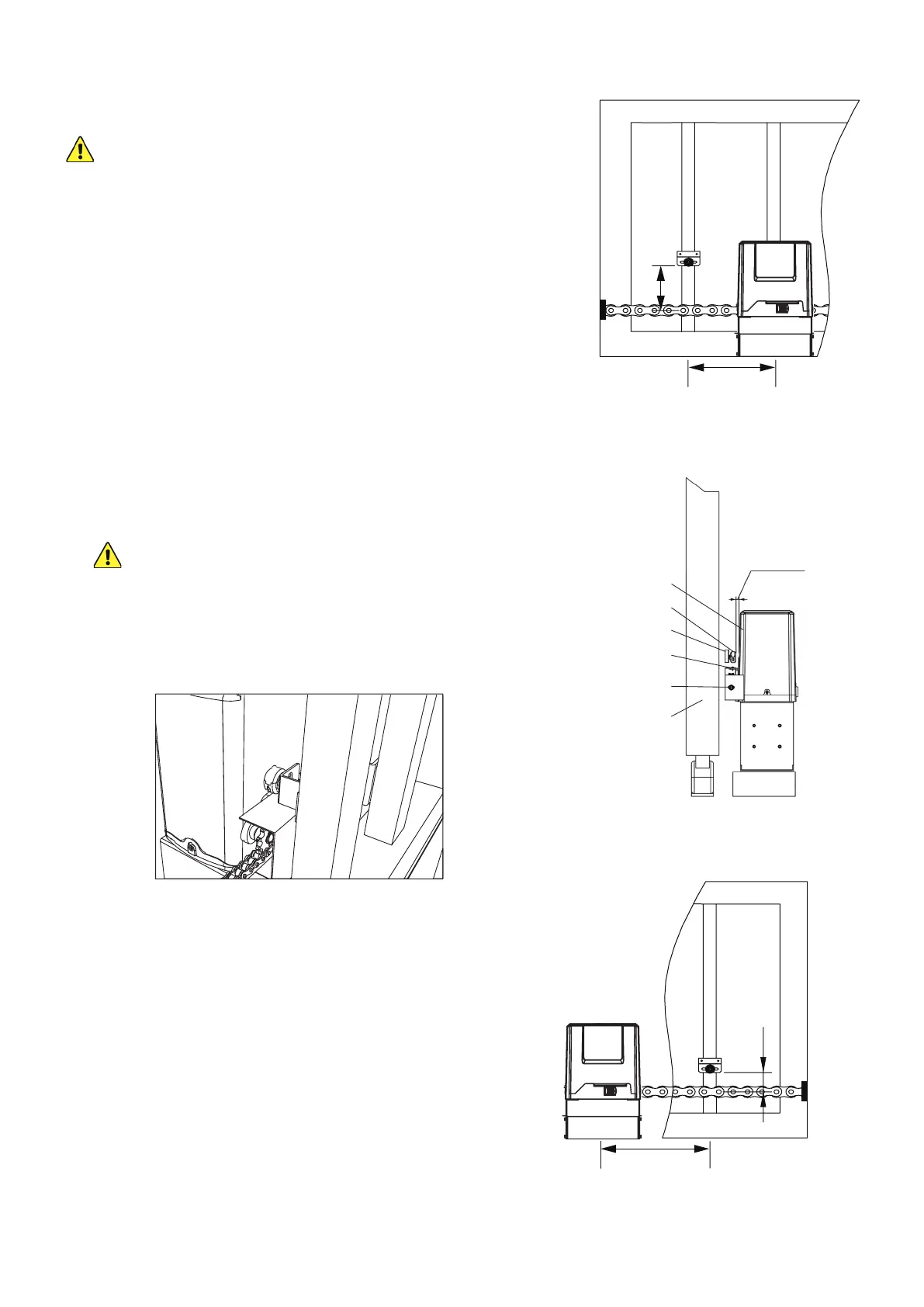
2. Find the post on the open gate about 6–8 inches
(15–20 cm) farther away from your driveway than the
middle of the motor.
3. Find the position on that post exactly 3.82 inches
(9.7 cm) above the middle of the taut chain.
4. Place one of the magnets (L) there using its bracket
andM6×65bolts(O),spring(U)andatwashers(S),
andnuts(Q)orusinganysimilarlysecureequipment.
The magnet should be held facing the opener with
at least 0.4 inches (1 cm) between it and the motor
casing.
The magnets and brackets are interchangeable
but the functions of their positions are not.
This higher magnet will function as the OPEN limit
switch because of the position of the sensors in
the motor housing. Reverse the diagrams shown in
Figures 18 and 20 for left side installation.
5. Move the gate to the position you want it to lock at
when fully closed.
6. Find the post on the closed gate about 6–8 inches
(15–20 cm) towards the driveway from the center of
your motor.
7. Find the position on that post exactly 1.38 inches
(3.5 cm) above the middle of the taut chain.
8. Place the other magnet there using its bracket and
fasteners or other similarly secure equipment as
before.
9. Fine tune the positions of the magnets during initial
testing (see below) so the system gently stops your
gate at the best location.
Motor
Magnet
Magnet Bracket
Chain
Sprockets
Gate
≤0.8in.(20mm)
6–8 in. (15–20 cm)
1.38 in. (3.5 cm)
3.82 in. (9.7 cm)
6–8 in. (15–20 cm)