AB 01 01/2009 page 14/26
5. Start up
Establish all connections described in chap. 4 prior to commissioning.
5.1 Settings at the Alarm Box AB 01
Following steps have to be carried out to make the Alarm Box AB 01 ready for operation:
• Switch the Alarm Box ON at the green main switch (1)
• Set switch (2) to position I to activate the buzzer for audible alarm
The unit is now ready for operation and notification.
5.2 Settings in APT-COM™ 3 DataControlSystem
5.2.1 Setting the tolerance limits in the APT-COM™ 3 measurement window
In the measurement windows of the chambers to be supervised, set appropriate limit values under “±
Limit Low/High”. The tolerance limits for the alarm can be set the measurement window individually for
each parameter of the corresponding measurement.
5.2.2 Connection of the Alarm Box AB 01 when operating APT-COM™ 3 and the Watch
Tool on the same computer
Connecting the Alarm Box to APT-COM™ 3
If APT-COM™ 3 and the Watch Tool are operated on a common computer, the Alarm Box AB 01 will be
connected to this computer.
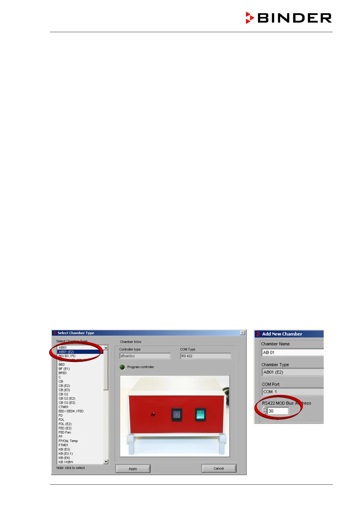
Configuration of the Alarm Box in APT-COM™ 3
Then the Alarm Box AB 01 must be configured like one of the connected temperature chambers in the
configuration menu “Chamber“ of APT-COM™ 3. Select “AB01 (E2)”. Enter “30” as RS422 device
address. The Alarm Box is managed and directly controlled by APT-COM™ 3.