Issue 02/2022 Art. No. 7001-0292
Operating Manual
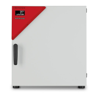
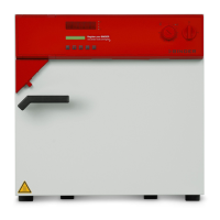
Avantgarde.Line with natural convection
Avantgarde.Line with forced convection
Avantgarde.Line with natural convection
Avantgarde.Line with forced convection
Avantgarde.Line with forced convection
and enhanced timer functions
with microprocessor temperature controller
Model Model version Art. No. Model Model version Art. No.
BD 56
BD056-230V 9010/ 9110-0323
ED 260
ED260-230V 9010/ 9110-0339
BD056UL-120V 9010/ 9110-0324 ED260UL-240V 9010/ 9110-0340
BD 115
BD115-230V 9010/ 9110-0325 ED 720 ED720-400V 9010/ 9110-0341
BD115UL-120V 9010/ 9110-0326
FD 56
FD056-230V 9010/ 9110-0303
BD 260
BD260-230V 9010/ 9110-0329 FD056UL-120V 9010/ 9110-0304
BD260UL-120V 9010/ 9110-0330
FD 115
FD115-230V 9010/ 9110-0305
BD 720
BD720-230V 9010/ 9110-0331 FD115UL-120V 9010/ 9110-0306
BD720UL-240V 9010/ 9110-0332
FD 260
FD260-230V 9010/ 9110-0309
BF 56
BF056-230V 9010/ 9110-0313 FD260UL-240V 9010/ 9110-0310
BF056UL-120V 9010/ 9110-0314 FD 720 FD720-400V 9010/ 9110-0311
BF 115
BF115-230V 9010/ 9110-0315
FED 56
FED056-230V 9010/ 9110-0295
BF115UL-120V 9010/ 9110-0316 FED056UL-120V 9010/ 9110-0296
BF 260
BF260-230V 9010/ 9110-0319
FED 115
FED115-230V 9010/ 9110-0293
BF260UL-120V 9010/ 9110-0320 FED115UL-120V 9010/ 9110-0294
BF 720
BF720-230V 9010/ 9110-0321
FED 260
FED260-230V 9010/ 9110-0299
BF720UL-240V 9010/ 9110-0322 FED260UL-240V 9010/ 9110-0300
ED 56
ED056-230V 9010/ 9110-0333
FED 720
FED720-400V 9010/ 9110-0301
ED056UL-120V 9010/ 9110-0334 FED720UL-208V 9010/ 9110-0302
ED 115
ED115-230V 9010/ 9110-0335
ED115UL-120V 9010/ 9110-0336
BINDER GmbH
Address: Post office box 102, 78502 Tuttlingen, Germany Phone: +49 7462 2005 0
Fax: +49 7462 2005 100 Internet: http://www.binder-world.com
E-mail: info@binder-world.com Service Hotline: +49 7462 2005 555
Service Fax: +49 7462 2005 93 555 Service E-Mail: customerservice@binder-world.com
Service Hotline USA: +1 866 885 9794 or +1 631 224 4340 x3
Service Hotline Asia Pacific: +852 390 705 04 or +852 390 705 03
Service Hotline Russia and CIS: +7 495 988 15 16