Operation
7
The health of the feedline and antenna systems can be monitored using VSWR
measurement under full power operating conditions. High VSWR is an indicator
of feed line damage, overtightened cable or feed line clamps, or antenna
changes/damage due to weather conditions, icing, or structural damage to the
tower.
Video Filter
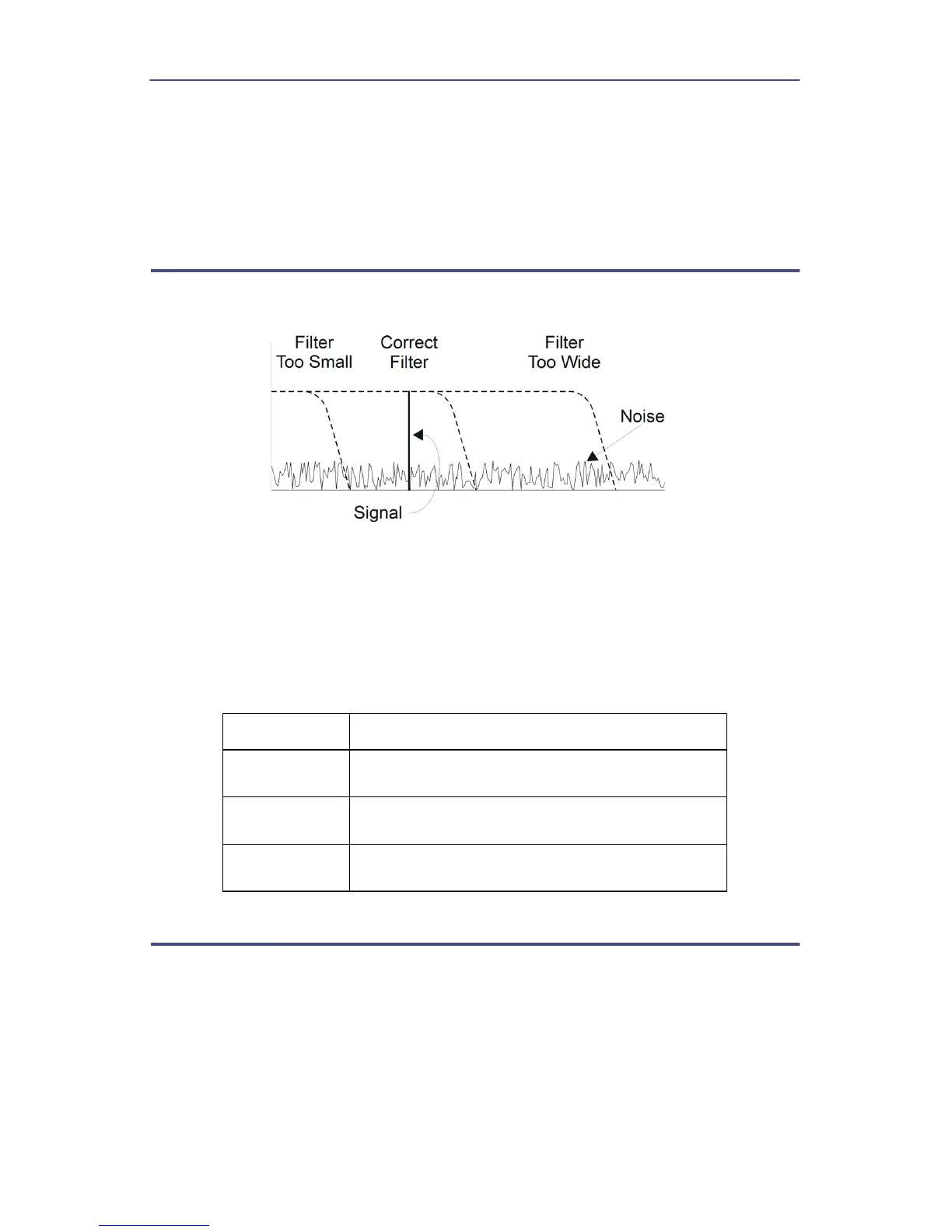
Figure 2 Video Filter Settings, 300 kHz Signal
Except for average power and VSWR measurements, all WPS measurements
rely on a variable video filter to improve accuracy. This filter can be set to either
4.5 kHz, 400 kHz, or full bandwidth. It should be as narrow as possible while still
being larger than the demodulated signal bandwidth (video bandwidth).
Narrowing the filter limits the noise contribution caused by interfering signals.
Listed below are some common modulation schemes and the appropriate video
filter.
Video Filter Modulation Type
4.5 kHz CW Burst (Burst width > 150 μs), Voice Band
AM, FM, Phase Modulation, Tetra
400 kHz CW Burst (b.w. > 3 μs), GSM, 50 kHz AM,
DQPSK
Full Bandwidth CW Burst (b.w. > 200 ns), CDMA, WCDMA,
DQPSK, DAB/DVB-T
Peak Envelope Power
Peak power measurements detect amplitude changes as a signal modulates the
carrier envelope. The WPS operates in an asynchronous cycle: 300 ms of
waveform sampling followed by a 50 ms reset period. The peak power is then
displayed and the cycle repeats. The display therefore updates about three
times per second.