ST-150-1 17
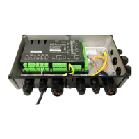
5 Electrical connection
Keep the compressor control module energized when
the motor is not running. This ensures an unloaded
start.
De-energize the module only for a long standstill period
of the compressor or for maintenance purposes.
5.1 Schematic wiring diagrams for star-delta start
Schematic wiring diagram see figure 1, page 18.
In the state of delivery, the time relay control is con-
figured for a star-delta motor. The compressor control
module controls the activation and deactivation times of
the motor contactors. The compressor starts 1seconds
after the release signal of the superior system control-
ler: The contact at terminal CN2:2 (K1 Control) closes
1second after the release signal and reopens after fur-
ther 2seconds. The contact at terminal CN2:1 (K2
Control) closes 1.5seconds after the release signal
and remains closed until the compressor is shut off.
5.2 Schematic wiring diagrams for soft start and
operation with frequency inverter
The schematic wiring diagram applies to soft start and
operation with frequency inverter. Only the main con-
tactor is required in both cases, see figure 2, page 19.
Therefore, the compressor control module must be
converted to direct-on-line start using the BEST Soft-
ware, see chapter Selecting the motor start function,
page 23.
Set the soft starter in a way to allow the motor to reach
its rated speed in less than 2 seconds.
Programm the frequency inverter in such a way to en-
sure that the compressor operated between 1500 and
4000 min
-1
. During commissioning, check the system
carefully in the entire frequency range for abnormal vi-
brations and skip critical frequencies.
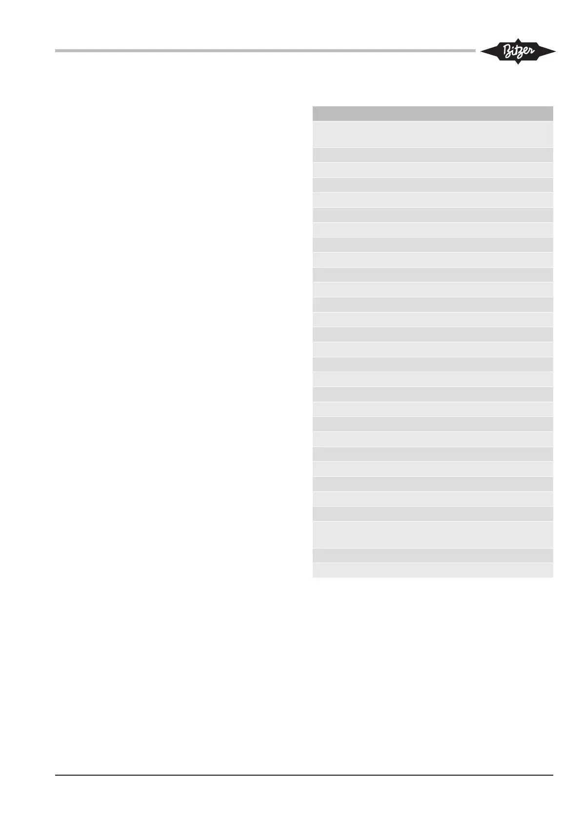
5.3 Legend for the schematic wiring diagrams
Abbr. Component
B2 Command for compressor start (release sig-
nal from system controller)
B5 Slider position indication
B6 High pressure transmitter
B7 Low pressure transmitter
F1 Main fuse
F2 Compressor fuse
F3 Control circuit fuse
F5 High pressure switch
F7 Oil monitoring (OLC-D1)
F13 Thermal overload "Motor"
F16 Rotation direction monitoring
F17 Control transformer fuse
H3 Signal lamp "compressor fault"
K1 Main contactor (Y/Δ or soft start)
K2 Delta contactor (Y/Δ)
K3 Star contactor (Y/Δ)
M1 Compressor
N1 Frequency inverter
N3 Soft starter
Q1 Main switch
R2 Discharge gas temperature sensor
S1 Control switch (on-off)
S2 Fault reset of CM-SW-01
T1 Control transformer (example for 230V)
Y4 Solenoid valve "capacity control CR+"
Y5 Solenoid valve "capacity control CR-"
Y9 Solenoid valve "oil return", optional connec-
tion
Y11 Solenoid valve "V
i
+"
Y12 Solenoid valve "V
i
-"
Tab.1: Components of the schematic wiring diagrams
 Loading...