ST-150-120
5.4 Wiring in the state of delivery
The following components are completely installed and
wired in the state of delivery:
• Slider position indication (B5)
• Oil monitoring (OLC-D1, F7)
• Solenoid valves for capacity control and V
i
(Y4, Y5,
Y11 and Y12)
• Discharge gas temperature sensor (R2)
• Low pressure and high pressure transmitters (B7
and B6)
These components are shown in grey in the schematic
wiring diagram. Modification to these components or
their wiring is not required and should not be done
without consulting BITZER.
The control module internally supplies the voltage to
peripheral devices (solenoid valves, oil monitoring
device and slider position indication) and to the terminal
strips CN7 to CN12.
5.5 High pressure limiter
According to EN 378 directive, each compressor must
be provided with a high pressure limiter (F5) for safety
cut-out in the safety chain. Depending on the refriger-
ant charge, it must be designed as a safety pressure
cut-out or only as pressure cut-out. The software-con-
trolled monitoring of the compressor control module via
the high pressure transmitter (B6) does not sufficiently
ensure the safety cut-out function. The high-pressure
limiter (F5) should preferably be connected to terminal
strip CN3 instead of the bridge.
The installation of a low pressure limiter is not neces-
sary. The compressor control module is provided with
an automatic low pressure cut-out function.
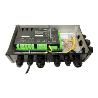
6 Connecting cables
Electrically connect the compressor control module in
accordance with the schematic wiring diagrams. Ob-
serve the safety standards EN 60204, IEC60364 and
national safety regulations.
Warning!
Risk of electrical shock!
Before working on the module housing and
electrical lines: Switch off the main switch and
secure it against being switched on again!
Close the module housing before switching on
again!
Notice!
The compressor control module may be dam-
aged or fail!
Never apply any voltage to the terminals of CN7
to CN12 – not even for test purposes!
The voltage applied to the terminals of CN13
must not exceed 10V!
The voltage applied to terminal 3 of CN14 must
not exceed 24V! Do no apply voltage to the
other terminals!
6.1 Required electrical connections
• Power connection to terminal strip CN1
– Terminal 1: L
– Terminal 2: N
• Command for compressor start (release signal from
the system controller, B2)
The release signal from the system controller is
provided in path 8 as the first link of the safety chain
in path 8. This release information must be passed
on to the compressor control device. It activates the
time relay control for the motor contactors K1, K2
and K3.
– Connect the safety chain (release signal) to ter-
minal strip CN2, terminal 3.
– Integrate the compressor control device as the
last link into the safety chain.
• Control signal from the system controller (nominal
value for capacity control)
– Connect the Modbus cable to terminal strip CN14.
– Or connect the analogue signal to terminal strip
CN13.
• High pressure limiter
– Connect it preferably to terminal strip CN3 instead
of the bridge (see schematic wiring diagrams).
– Alternatively, it can also be integrated into the
safety chain; in that case after the compressor
control module.
6.2 Optional electrical connections
A solenoid valve can be connected to terminal strip
CN4 for dosing the oil return (Y9). It is switched by the
compressor control module. this function is not
available at the moment.
 Loading...