ST-150-1 21
6.3 Connecting system controller
6.3.1 Control via analogue signal
The compressor capacity is regulated via a DC voltage
signal. This type of control is mainly suitable for sys-
tems with simple controllers which are equipped with
an output for 0 to 10V and a relay, and for use in com-
bination with the BEST Software.
• Connection to terminal strip CN13, terminals 1 and
2.
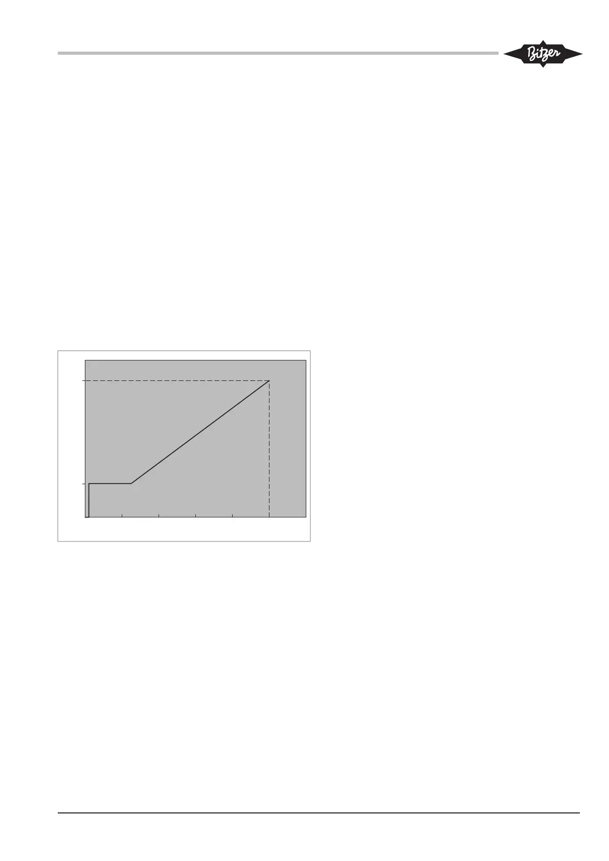
• Control signal: 0 to 10V DC voltage of an analogue
output of the system controller
• Control accuracy: ±0.5% at 100%
• Linear control characteristic, see figure.
• For compressor start the release signal from the sys-
tem controller and a set point signal >2% is re-
quired.
CR
0 2 4 6 8 10 12
U [V]
0 .. 10 V
100%
25%
0,2
2%
Fig.3: Control characteristics
6.3.2 Control via Modbus interface
Plug or connect the cable to terminal strip CN14. See
schematic wiring diagrams.
In this case, the operating parameters cannot be mon-
itored by means of the BEST Software.
6.4 Operation monitoring with the BEST Software
• Connect the BEST interface converter to terminal
strip CN14 (Modbus).
In this case, the capacity control must be done via the
analogue signal from terminal strip CN13.
7 Protective functions
The green LED is on during normal operation. The
LEDs can be seen through a sight glass on the right
side of the module housing.
Before the measured parameter of a sensor reaches a
critical threshold, the compressor control module out-
puts a warning signal via the Modbus RS485 interface
(CN14). In this case, the yellow LED lights up. Once a
measured parameter is considerably outside the allow-
able range, the compressor control module immediately
switches off the motor. The red LED lights up.
The blue LED lights up when data are transmitted via
the Modbus interface.
Depending on the measured parameter, up to 3 alarm
levels are defined. These alarms are recorded and dis-
played using the BEST Software. The alarm levels al-
low a system controller to be programmed in a way that
allows the compressor to be adjusted within the applic-
ation limits.
Warning
The warning threshold is exceeded when the applica-
tion limit is almost reached. The yellow LED lights up.
This is a software message, not a safety reference. The
warning refers exclusively to the critical operating con-
dition of the compressor.
Critical alarm
The cut-out value is exceeded. The yellow LED lights
up. If the corresponding measured value does not drop
again within 30 seconds, the compressor will be
switched off. This cut-out is classified as fault in the
alarm list.
Fault
The cut-out value has been exceeded too much or for
too long. The compressor is switched off. The red LED
lights up.
 Loading...