SB-170-9 RUS
57
SB-170-9 25
5
.4.2 CM-SW-01
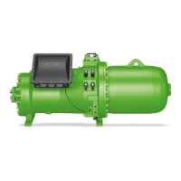
Standard for all CSW105 compressors
The compressor module integrates the entire electronic
periphery of the compressor: It allows monitoring the
essential operating parameters of the compressor: mo-
tor and discharge gas temperature, phase and rotation
direction monitoring, oil supply and application limits
and thus protects the compressor from operation under
critical conditions. For further information, see Tech-
nical Information ST-150.
NOTICE
The compressor module may be damaged or
fail!
Never apply any voltage to the terminals of CN7
to CN12 – not even for test purposes!
The voltage applied to the terminals of CN13
must not exceed 10V!
The voltage applied to terminal 3 of CN14 must
not exceed 24V! Do no apply voltage to the
other terminals!
The following components are completely installed and
wired in the state of delivery:
• Slider position indicator.
• Oil monitoring (OLC-D1).
• Solenoid valves for capacity control and V
i
.
• Discharge gas temperature sensor.
• Low pressure and high pressure transmitter.
Modification to these components or their wiring is not
required and should not be done without consulting
BITZER.
The following components are not installed and wired in
the state of delivery and need to be connected:
• Motor temperature monitoring (PTC sensor in motor
winding).
• Phase monitoring (in case of a phase failure or inad-
missibly high phase asymmetry).
The compressor module internally supplies voltage to
the peripheral devices (solenoid valves, oil monitoring
device and slider position indicator) and to the terminal
strips CN7 to CN12.
Please refer to the Technical Information ST-150 for in-
formation on all connections.
5
.4.3 SE-i1
This protection device with extended monitoring func-
tions can be used as an option for all HS.53 .. HS.85
compressors and CSH and CSW compressors.
Monitoring functions:
• Temperature monitoring.
• Monitoring of the PTC control circuit to detect any
short-circuit or line break/sensor failure.
• Rotation direction monitoring.
• Monitoring of phase failure and asymmetry.
• Monitoring of the maximum cycling rate.
For further information, see Technical Information
CT-110.
5
.4.4 SE-E2
Optional protection device for operation with frequency
inverter and soft starter (for a ramp time shorter than
1s).
• Dimensions and integration in the control identical to
SE-E1.
• Suitable for all CS. compressors.
• Monitoring functions are basically identical to those
of SE-E1. However, the SE-E2 monitors phase fail-
ure during the entire running time of the compressor.
For further information, see Technical Information
ST-122.
5
.4.5 Monitoring of the oil circuit
• For short circuits without liquid injection (LI) for addi-
tional cooling and for small system volume and small
refrigerant charge: Indirect monitoring with oil tem-
perature sensor (standard)
NOTICE
Lack of oil leads to a too high increase in tem-
perature.
Risk of damage to the compressor!
• For circuits with liquid injection (LI) for additional
cooling and / or for great system volume as well as
parallel compounding: Monitor oil level directly with
opto-electronic oil level monitoring (option), see
chapter Opto-electronic oil level monitoring OLC-D1-
S, page 26. The connection is on the compressor
housing, see chapter Connections and dimensional
drawings, page 14, position 8.
5.2 Motorausführungen
HINWEIS
Gefahr von Verdichterausfall!
Verdichter nur in der vorgeschriebenen Dreh-
richtung betreiben!
Die Verdichter-Baureihen CS.65, CS.75, CS.85,
CSH76 und CSH86 sind standardmäßig mit Teilwick-
lungsmotoren (Part Winding "PW") in Δ/ΔΔ-Schaltung
ausgerüstet. Als Sonderausführung sind alternativ auch
Stern-Dreieck- Motoren (Y/Δ) lieferbar. Detailinforma-
tionen siehe Handbuch SH-170.
Die CS.95-, CSH96- und CSW105-Modelle sind gene-
rell mit Stern-Dreieck-Motoren (Y/Δ) ausgestattet.
T
eilwicklungsmotoren (PW)
Anlaufmethoden:
• Teilwicklungsanlauf zur Minderung des Anlauf-
stroms.
• Direktanlauf.
Zeitverzögerung bis zum Zuschalten der 2. Teilwick-
lung: max.0,5s!
Anschlüsse korrekt ausführen! Vertauschte Anordnung
der elektrischen Anschlüsse führt zu gegenläufigen
oder im Phasenwinkel verschobenen Drehfeldern und
dadurch zu Blockierung des Motors!
Motorklemmen gemäß Anweisung auf dem Deckel des
Anschlusskastens anschließen.
Reihenfolge der Teilwicklungen unbedingt beachten!
• 1. Teilwicklung (Schütz K1): Anschlüsse 1 / 2 / 3.
• 2. Teilwicklung (Schütz K2): Anschlüsse 7 / 8 / 9.
• Wicklungsteilung 50%/50%.
• Motorschützauslegung:
– 1. Schütz (PW 1): 60% des max. Betriebsstroms.
– 2. Schütz (PW 2): 60% des max. Betriebsstroms.
S
tern-Dreieck-Motor
Die Zeitverzögerung vom Einschalten des Verdichters
bis zum Umschalten von Stern- auf Dreieck-Betrieb
darf 2s nicht übersteigen.
Anschlüsse korrekt ausführen!
Vertauschte Anordnung der elektrischen Anschlüsse
führt zu Kurzschluss!
Information
Netz- und Dreieckschütz auf jeweils mindestens
60%, das Sternschütz auf 33% des max. Be-
triebsstroms bemessen.
5
.3 Hochspannungsprüfung
(Isolationsfestigkeitsprüfung)
Die Verdichter wurden bereits im Werk einer Hoch-
spannungsprüfung entsprechend EN12693 bzw. ent-
sprechend UL984 bzw. UL60335-2-34 bei UL-Ausfüh-
rung unterzogen.
HINWEIS
Gefahr von Isolationsschaden und Motorausfall!
Hochspannungsprüfung keinesfalls in gleicher
Weise wiederholen!
Eine erneute Hochspannungsprüfung darf nur mit max.
1000 V ∿ durchgeführt werden.
5
.4 Schutzgeräte
WARNUNG
Gefahr von elektrischem Schlag!
Vor Arbeiten im Anschlusskasten des Verdich-
ters: Hauptschalter ausschalten und gegen Wie-
dereinschalten sichern!
Vor Wiedereinschalten Anschlusskasten des
Verdichters schließen!
HINWEIS
Ausfall des Schutzgeräts und des Motors durch
fehlerhaften Anschluss und/oder Fehlbedienung
möglich!
Anschlüsse gemäß Prinzipschaltbildern korrekt
ausführen und auf festen Sitz prüfen.
Kabel und Klemmen des PTC-Messkreises dür-
fen nicht mit Steuer- oder Betriebsspannung in
Berührung kommen!
5.4.1 SE-E1
Dieses Schutzgerät ist serienmäßig im Anschlusskas-
ten aller HS.53 .. HS.85-Verdichter und CSH-, CSW-
Verdichter fest eingebaut. Die Kabel für die Überwa-
chung von Motor- und Öltemperatur sowie von Dreh-
richtung und Phasenausfall sind im Auslieferungszu-
stand an der Stromdurchführungsplatte angeschlossen.
Weitere Anschlüsse gemäß Prinzipschaltbild im An-
schlusskasten, Handbuch SH-170 und Technischer In-
formation ST-120.
Überwachungsfunktionen:
• Temperaturüberwachung.
• Drehrichtungsüberwachung.
• Phasenausfallüberwachung.
 Loading...


