14
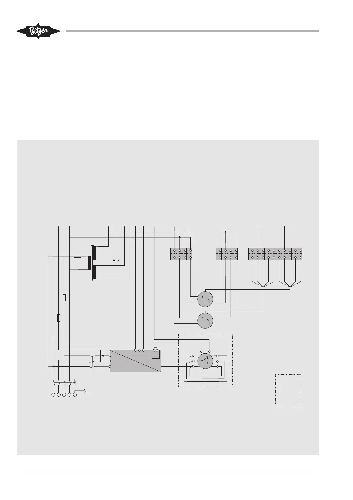
Internal cabling
These two pages represents the inter-
nal electrical connections of a LHV.E
condensing unit.
Optional accessory
Signal lamp "operation"
Signal lamp "failure"
Setpoint adjustment
Legend of components see page 16.
Câblage interne
Dans ces deux pages voir schématique-
ment les raccordements électriques
internes du groupe de condensation
LHV.E.
Accessoire optionnelle
Lampe "fonctionnement"
Lampe "défaut"
Ajustement de la valeur de consigne
Légende des composants voir page 16.
Interne Verkabelung
Auf diesen beiden Seiten sind die
internen elektrischen Anschlüsse
eines LHV.E- Verflüssigungssatzes
schematisch dargestellt.
Optionales Zubehör
Signallampe "Betrieb"
Signallampe "Störung"
Sollwertjustierung
Legende der Bauteile siehe Seite 16.
KT-203-1
X101
28
27
246
23
28
27
24
23
24 V AC-1
230 VB
K1T2F1
X100/2
Mcpr/1
Mcpr/2
X100/3
X100/1
N
24 V AC-2
NB
M1
Mcpr
L1
PE
L2
L3
N
Q1
1
0
3
3
L1
L3
L2
K1
20
X101
1
2
3
SDI1
M
3
U1
W1
U2 V2W2
V1
J
1
6
3
5
1
1
3
3
schwarz/black/noir
T3
N
5
T1
4
T2
62
2
rot/red/rouge
NB
24VAC-1
24VAC-2
230VB
FAN1-NC
230VB
2
4
T 500mA
230VAC
230VAC
24VAC
F3
1
2
F1
T 6,3A
12
FAN1-NC
FAN2-NC
N1
T1
M2
Mfan1
Mfan2
M3
M 1
M 1
FAN2-NC
230VB
weiß/white/blanc
weiß/white/blanc
weiß/white/blanc
weiß/white/blanc
FAN2-L
N
X101
30
29
26
25
30
29
26
25
FAN1-L
N
schwarz/black/noir
blau/blue/bleu
schwarz/black/noir
blau/blue/bleu
FAN2-L
FAN1-L
SDI2
RJ45
weiß/whithe/blanc
M1
M2
12
3
4
5
6
7
8
F2
T 6,3A
12
F4
T 4A
12
L2F4
K1T3F2
Details zum Anschluss siehe
Innenseite des Anschlusskastens.
Details concerning connections
see inside the terminal box.
Détails sur le raccordement voir
intérieur de la boîte de raccordement.
X102
6
8
16
7
6
8
16
7
15
14
5
13
15
14
5
13
4
12
4
12
rot/red/rouge
gelb/yellow/jaune
blau/blue/bleu
weiß/white/blanc
weiß/white/blanc
rot/red/rouge
gelb/yellow/jaune
blau/blue/bleu
weiß/white/blanc
weiß/white/blanc
FAN1-10V
FAN1-CTRL
GND
FAN2-10V
FAN2-CTRL
GND
FAN2-RSA
FAN1-RSA
FAN2-RSB
FAN1-RSB
FAN1-CTRL
GND
FAN2-CTRL
GND
Data+
Data-
GND