8 KT-200-2
3 Electrical connection
In the terminal box of the condensing
unit the system control and the
optional OLC-K1 are prewired (fig. 4,
thin lines). The optional cold store
temperature sensor R5 as well as all
other system components (H2, H3, S2,
S5, S6 or Y1) have to be connected on
site (bold lines). Double layer terminal
strips simplify the connection and
identification of the cables
(components X101 and X102).
ll electrical connections are to be
made according to figure 4 and the
schematic wiring diagrams.
3 電気接続
コンデンシングユニットの端子ボックス
には、システム制御とオプションのOLC-K1
があらかじめ配線されています(図4、細い
線)。オプションの冷蔵室温度センサー
R5とその他のすべてのシステムコンポー
ネント(H2、H3、S2、S5、S6、Y1)は
設置場所で接続する必要があります
(太い線)。2層端子ストリップを使用す
れば、ケーブルの接続と識別を簡単に行
えるようになります(コンポーネント
X101とX102)。
電気接続はすべて、図4および配線図に
従って行ってください。
Caution!
High voltage!
The most terminals of terminal
strip X101 are energized by 230 V
when condensing unit is switched
on.
Before working on the electrics,
switch off main switch of
condensing unit!
警戒!
高い電圧がかかっています。
端子ストリップX101のほとんどの
端子には、コンデンシングユニット
がオンになると230 Vの電圧がかか
ります。
電気系統の作業を行う前にコンデン
シングユニットのメインスイッチを
オフにしてください。
!
!
Attention!
Protect controller B1 from
overvoltage!
Use screened cables for the
connection of setpoint
adjustment, digital inputs DI1 &
DI2 (S5, S6) and cold store
temperature sensor (R5)!
!
!
注意!
コントローラーB1を過電圧から保
護してください。
設定値調整、デジタル入力DI1&DI2
(S5、S6)、冷蔵室温度センサー
(R5)の接続には、シールドケーブ
ルを使用してください。
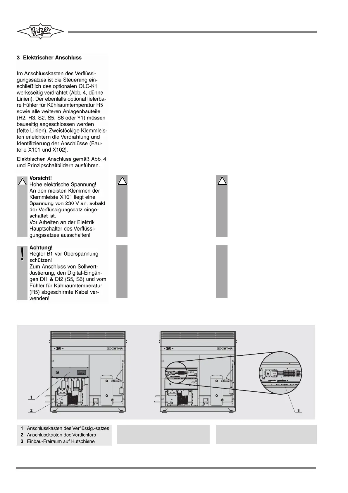
Position der Anschlusskästen Position of terminal boxes
端子ボックスの位置
1 Terminal box of condensing unit
2 Terminal box of compressor
3 Free space for mounting on top hat rail
1 コンデンシングユニットの端子ボックス
2 コンプレッサーの端子ボックス
3 トップハットレール上の取付けスペース
Fig. 3 Terminal boxes Fig. 3 Terminal boxes
図 3 端子ボックス
 Loading...