11
Operang Instrucons - BPS2000v2 Monitoring Power Distribuon Unit
f
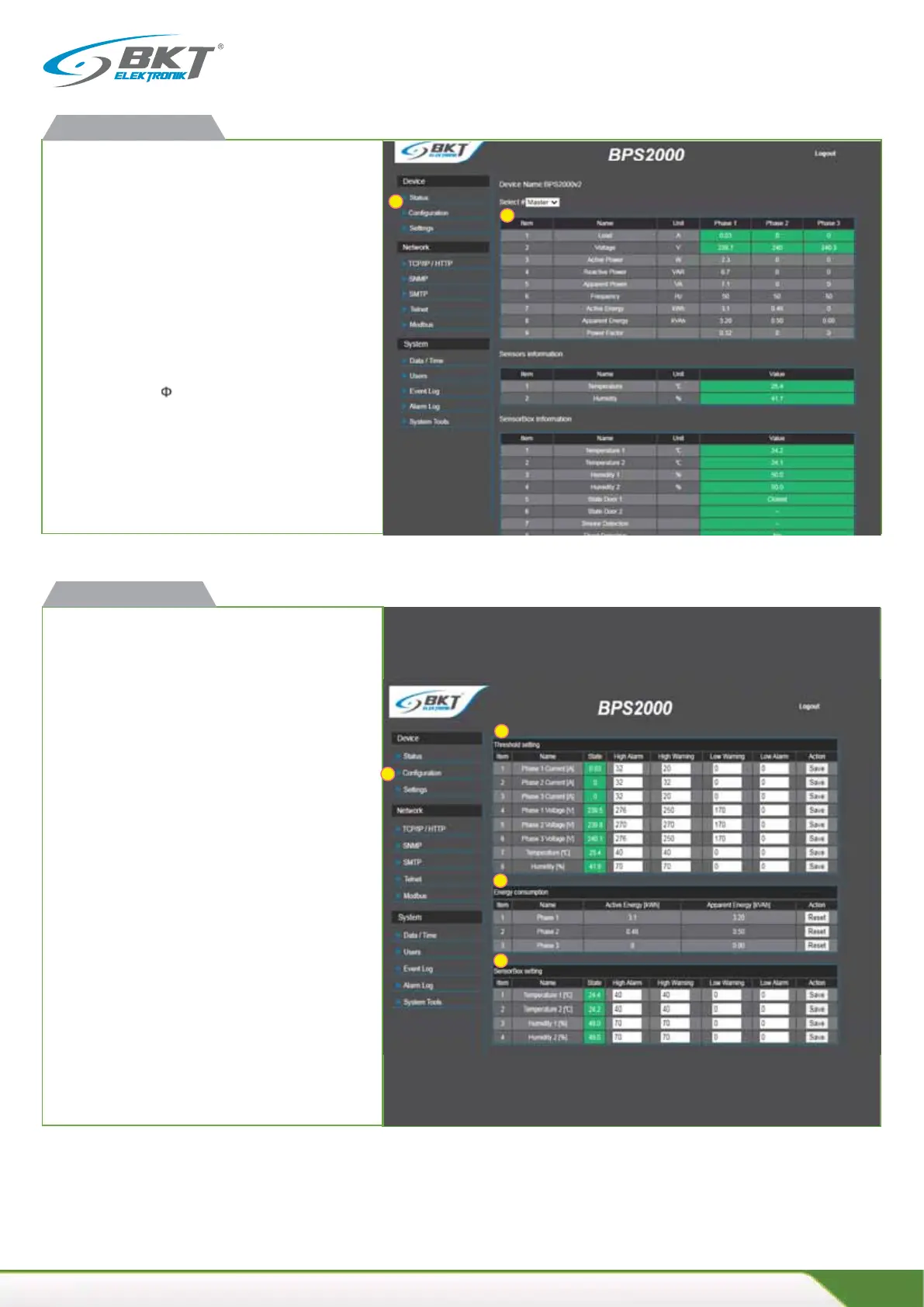
Available readings
x current load for each phase [A]
x supply voltage for each phase[V]
x acve power for each phase [W]
x reacve power for each phase [VAR]
x apparent power for each phase [VA]
x acve energy meters for each phase [kWh]
x apparent energy meters for each phase [kVAh]
x power factor (cos )
x frequency [Hz]
x temperature and humidity
Green color indicates normal state.
Orange color means warning state exceeded.
Red color means alarm state exceeded.
BPS2000v2 web interface
f
Configuraon
1. Alarm thresholds configuraon
x total load for each phase [A]
x supply voltages for each phase [V]
x temperature and humidity
2. Energy consumpon measurement
Click the "Reset" buon to reset the energy meter for each
phase.
Reseng the energy meters requires confirmaon with the
password of the administrator.
3. Configuraon of alarm thresholds for the module
SensorBox environmental condions
x temperature and humidity from port 1 of the SensorBox
module
x temperature and humidity from port 2 of the SensorBox
module
BPS2000v2 web interface
2
3
1
2
1
1
2
3