16
1. 8 7 7. 8 7 7. 2 269 BLACKBOX.COM
NEED HELP?
LEAVE THE TECH TO US
LIVE 24/7
TECHNICAL
SUPPORT
1.877.877.2269
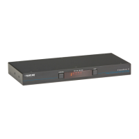
4. Audio: Where required, connect the lead from your speakers to the audio socket. See Figure 3-3.
Figure 3-3. Connecting speakers to the user console.
3.3.1.1 SUPPORT FOR OPTICAL S/PDIF AUDIO
The Line In sockets on the computer ports and the Line Out socket on the user console are dual purpose. They can accept either
3.5mm analog jacks or mini- TOSLINK optical fiber connectors. The latter provide access to the optical S/PDIF (Sony/Philips Digital
InterFace) capabilities supported by the Freedom II system, which switches PCM (Pulse Code Modulation) audio at 96KHz.
3.3.2 COMPUTER SYSTEMS
Each computer system is connected to the Freedom II unit using (up to) two cables. Freedom II switches support USB 2.0 (incl. USB
1.1) connections.
TO CONNECT A COMPUTER SYSTEM
1. Ensure that power is disconnected from the Freedom II unit and the system to be connected.
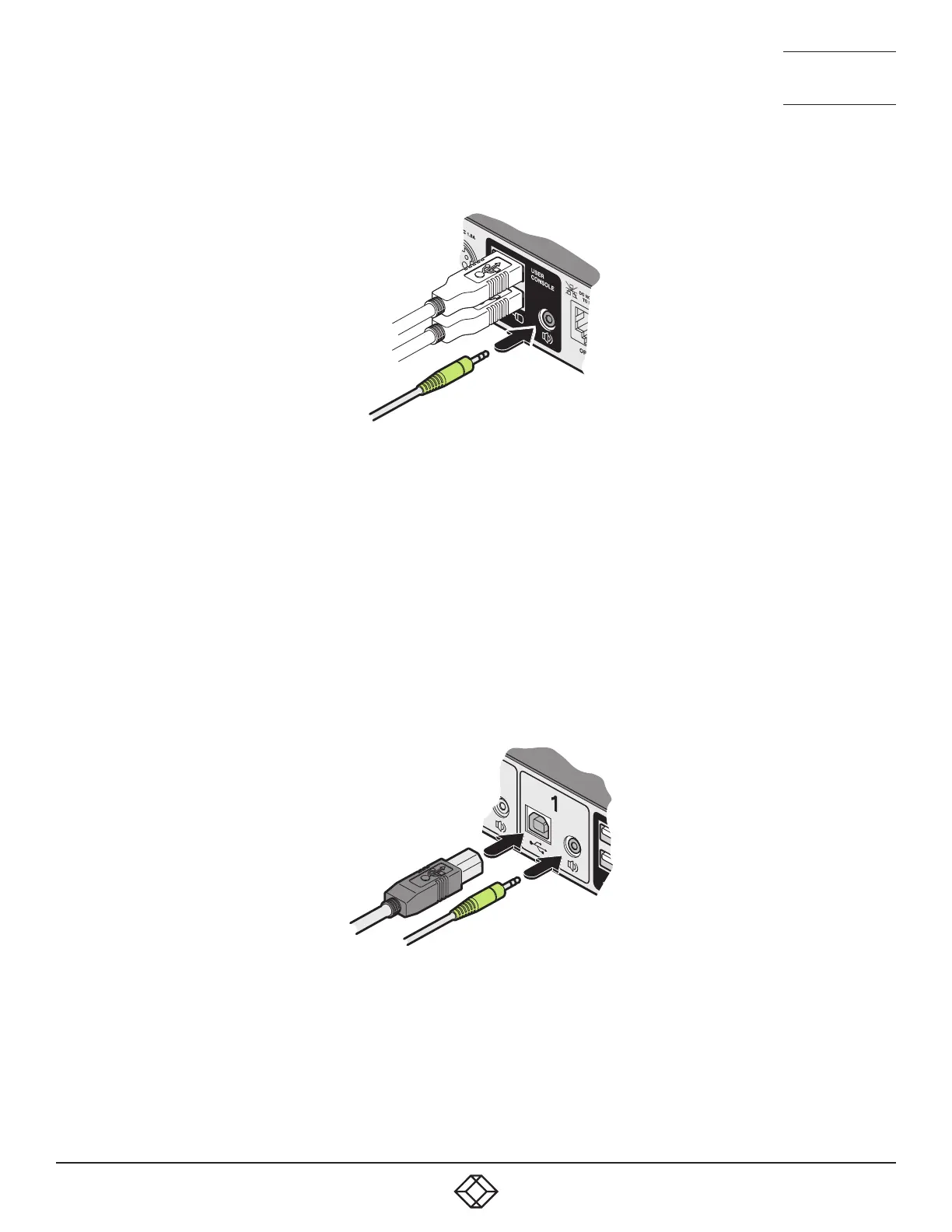
2. Use a USB cable (type-A to type-B) to link a USB port on the computer system to the USB port of the required channel on the rear
of the unit. See Figure 3-4.
Figure 3-4. Connecting the USB and speaker leads from a computer to the Freedom II unit.
3. If required, use a stereo audio link cable (3.5-mm jacks at either end) to link the speaker port on the computer system to the audio
port of the required channel on the rear of the unit. See Figure 3-4.
 Loading...